User’s Manual 3300565
3300565 User’s Manual Copyright Copyright 2006. All rights reserved. This document is copyrighted and all rights are reserved. The information in this document is subject to change without prior notice to make improvements to the products. This document contains proprietary information and protected by copyright. No part of this document may be reproduced, copied, or translated in any form or any means without prior written permission of the manufacturer.
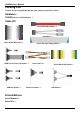
300565 User’s Manual Packing List Please check the package before you starting setup the system Hardware: 3300565 series motherboard x 1 Cable Kit: Serial ATA Ribbon Cable x 2 PS2 Cable x 1 44-pin ATA33 IDE Cable x 1 26-pin Slim Type Floppy Cable x 1 COM Port & Printer Port Cable x 1 COM Port Cable x 1 Power Cable x 1 Audio Port Cable x 1 40-pin ATA100 IDE Cable x 1 USB Cable x 1 Printed Matters: User’s Manual x 1 Driver CD x 1 3
3300565 User’s Manual Index Chapter 1 ..................................................................................... 7 1.1 ................................................................................. 7 1.2 ........................................................................... 8 1.3 ....................................................................... …10 1.4 .......................................
3300565 User’s Manual 2.15.1 .......................................................................... 33 2.15.2 ...................................................................... 34 2.16 ......................................................................... 35 Chapter 3 ................................................................... 37 3.1 ............
3300565 User’s Manual (The Page is Left For Blank) 6
3300565 User’s Manual Introduction Chapter 1 1.1 3300565 is the 5.25 inch embedded miniboard based on VIA chipset. It integrates VIA embedded chipset for CN700 with VT8237R Plus, DDR 333/400 SDRAM, and serial ATA with RAID to provide the economical embedded platform. VIA CN700 & VT8237R Plus Chipset The board comes with the VIA embedded chipset of CN700, supports DDR 333/400 SDRAM, integrated the S3 Graphics UniChrome Pro IGP graphics core, hardware MPEG-2 acceleration.
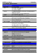
3300565 User’s Manual Introduction 1.2 General Specification Form Factor CPU Memory Chipset BIOS Green Function Watchdog Timer Real Time Clock Enhanced IDE Serial ATA 5.25 inch miniboard VIA V4/Eden 1.0GHz processor L1/L2 Cache: 128/128KB Front side bus: 400MHz 1 x 184-pin DDR 333/400 SDRAM up to 1GB,onboard optional 256MB DDR SDRAM Unbufferred, none-ECC memory supported only VIA CN700 and VT8237R Plus Phoenix-Award v6.
3300565 User’s Manual Introduction Ethernet Interface Chipset Type Connector REALTEK 8110S-32 10Base-T / 100Base-TX /1000Base-TX auto-switching Fast Ethernet Full duplex, IEEE802.3U compliant Four External RJ45 connectors with LED on rear I/O panel Audio Interface Chipset Interface Connector REALTEK ALC655 5.
3300565 User’s Manual Introduction 1.
3300565 User’s Manual Introduction 1.4 Eden nanoBGA2 CRT/LCD Monitor VT1636 LVDS 1 x 184-pin DDR333/400 Up to 1GB CN700 Ultra V-Link 533MB/s 6 x USB2.
3300565 User’s Manual Hardware Setup Chapter 2 2.
3300565 User’s Manual Hardware Setup CF DC_IN Connector Location LAN1/2/3/4 COM1 USB CRT 13
3300565 User’s Manual Hardware Setup 2.
3300565 User’s Manual Hardware Setup 2.3 2.3.
3300565 User’s Manual Hardware Setup 2.4 2.4.1< CPU> The board supports VIA Eden processor, default ratio is Eden 1G (400MHz) with heatsink only. 2.4.2 The board supports one 184-pin DDR333/400 SDRAM and up to 1GB of capacity, only non-ECC, unbuffered memory is supported. DIMM 104-pin 80-pin Please check the pin number to match the socket side well before installing memory module.
3300565 User’s Manual Hardware Setup 2.5 The board’s data of CMOS can be setting in BIOS. If the board refuses to boot due to inappropriate CMOS settings, here is how to proceed to clear (reset) the CMOS to its default values.
3300565 User’s Manual Hardware Setup 2.6 The board supports two enhanced IDE interface, dual channel for 4 ATAPI devices with ATA33. Based on embedded application, the board has one 44-pin IDE connector +5V supported for disk on module. The board also provides a Compact Flash Type II socket with jumper (JCFSEL) selectable slave/Master mode on secondary IDE channel.
3300565 User’s Manual Hardware Setup 2.7 Based on VIA VT8237R Plus Southbridge, the board supports two Serial ATA interfaces with RAID 0 and 1 array function. The following is the list of the specification of the Serial ATA. 1. Complies with Serial ATA Specification Revision 1.0 2. Dual Channel master mode PCI 3. On-chip two-channel Serial ATA (S-ATA) PHY for support of up to two S-ATA devices directly. 4.
3300565 User’s Manual Hardware Setup 2.8 The board provides a slim type floppy port; please use the 26-pin ribbon cable in the package to connect the floppy device. FDD Floppy rear side 4. Lift up this plastic bar 5. Slot the cable in (Blue paste for outside) 6. Press back the plastic bar 1. 2. Lift up the brown plastic bar Slot the cable in (Blue paste for 3.
3300565 User’s Manual Hardware Setup 2.9 The board provides four GigaLAN interfaces with REALTEK 8110S-32 PCI controller, and compliant with standard IEEE 802.3 Ethernet interface for 100BASE-TX.
3300565 User’s Manual Hardware Setup 2.10 Based on VIA CN700, the board supports integrated S3 Graphics UniChrome Pro IGP graphics, with BIOS selectable 16/32/64MB shared with system memory for frame buffer. 2.10.1 The board provides a DB15 CRT connector on the rear I/O panel.
3300565 User’s Manual Hardware Setup 2.10.
3300565 User’s Manual Connector: CN_INV Type: 5-pin LVDS Power Header Connector model: JST B5B-XH-A Pin Description 1 +12V 2 GND 3 GND 4 5 Hardware Setup Connector: JVLCD Type: 3-pin Power select Header Pin 1 2 3 GND ENABKL Connector: CN_LVDS Type: onboard 40-pin connector for LVDS connector Connector model: HIROSE DF13-40DP-1.
3300565 User’s Manual Hardware Setup To setup the LCD, you need the component below: 1. A panel with LVDS interfaces. 2. An inverter for panel’s backlight power. 3. A LCD cable and an inverter cable. For the cables, please follow the pin assignment of the connector to make a cable, because every panel has its own pin assignment, so we do not provide a standard cable; please find a local cable manufacture to make cables. LCD Installation Guide: 1.
3300565 User’s Manual Hardware Setup After setup the devices well, you need to select the LCD panel type in the BIOS. The panel type mapping is list below: 3300565 BIOS panel type selection form VGA ROM VERSION: 9Y-9X-00-20 NO.
3300565 User’s Manual Hardware Setup 2.11 The board provides the onboard AC97 5.1-channel audio interface with Realteck ALC655. Connector: CN_AUDIO Type: 10-pin (2 x 5) header (pitch = 2.54mm) Pin Description Pin 1 Line/SURR – Left 2 3 Line/SURR – Right 4 5 MIC2/LEF 6 7 N/C 8 9 Line Out – Right 10 Description Ground MIC1/CEN Ground Line Out– Left Ground Connector: CDIN Type: 4-pin header (pitch = 2.
3300565 User’s Manual Hardware Setup 2.12 Based on VIA VT8237R Plus, the board provides 6 USB2.0 ports. The USB2.0 interface provides up to 480Mbps of transferring rate. Interface USB2.0 Controller VIA VT8237R+ Transfer Rate Up to 480Mb/s Output Voltage 500mA 1 CN_USB 10 USB 28 USB2.
3300565 User’s Manual Connector: CN_USB Type: 10-pin (5 x 2) header for USB2/3 Ports Pin Description Pin 1 VCC 2 3 Data04 5 Data0+ 6 7 Ground 8 9 Ground 10 Hardware Setup Description VCC Data1Data1+ Ground N/C PS: The USB2.0 will be only active when you connecting with the USB2.0 devices, if you insert an USB1.1 device, the port will be changed to USB1.1 protocol automatically. The transferring rate of USB2.0 as 480Mbps is depending on device capacity, exact transferring rate may not be up to 480Mbps.
3300565 User’s Manual Hardware Setup 2.13 The board provides a programmable 8-bit digital I/O interface; you can use this general purpose I/O port for system control like POS or KIOSK. Connector: CN_DIO Type: onboard 2 x 6-pin header, pitch=2.
3300565 User’s Manual Hardware Setup 2.14 The board provides four RS232 serial ports, with jumper selectable RS422/485 for COM2.
3300565 User’s Manual Hardware Setup JCSEL2 JCSEL1 CN_COM2/3/4 1 10 COM 32 GPIO Interface
00565 User’s Manual Hardware Setup 2.15 The board comes with a 2-pin DC-Jack power connector for DC 12V input, it also has one 4-pin P4 additional use power connector for internal power supply, you can choose one pf them to meet your pplication. 2.15.
3300565 User’s Manual Hardware Setup 2.15.2 Connector: CN_PWR Type: 4-pin P-type connector for +5V/+12V output Pin Description Pin Description Pin 1 +5V 2 Ground 3 Note: Maximum output voltage: 12V/5A & 5V/3A Description Ground Floppy Pin 4 Description +12V ATAPI Drives Relative Accessory 2.15.
3300565 User’s Manual Hardware Setup 2.16 The JFRNT provides front control panel of the board, such as power button, reset and beeper, etc. Please check well before you connecting the cables on the chassis. Connector: JFRNT Type: onboard 14-pin (2 x 7) 2.
3300565 User’s Manual (This Page is Left For Blank) 36
3300565 User’s Manual System Configuration Chapter 3 3.1 The board supports two Serial ATA ports onboard, and supports RAID 0, 1 and JBOD disk array, the RAID 0, 1 and JBOD are specified below: RAID 0 (Stripping): Two hard drives operating as one drive for optimized data R/W performance. It needs two unused drives to build this operation.
3300565 User’s Manual You also can edit disk array under OS, please install the VIA RAID Utility in the driver CD.
3300565 User’s Manual System Configuration 3.2
3300565 User’s Manual 3.3 The board provides onboard analog VGA interface, and optional digital display interface with LVDS , please install the VIA video driver before enjoy the vivid display. Based on the VIA CN700 with S3 UniChrome Pro graphic, the board provides dual display function for clone or extended desktop modes with secondary display device attached. After installing video driver, please launch the desktop display properties.
3300565 User’s Manual System Configuration Two controllers for each display device There are two options for secondary display device For more display properties setting, please click “Advanced” button.
3300565 User’s Manual Please select S3Display for advanced device setting. Connected Devices Click check box to enable/disable device Specified display setup if available When you set dual display clone mode, you’ll see the same screen display on two devices. When you set the dual display for extended desktop mode, you can have the independent desktop on the second device.
3300565 User’s Manual (This Page is Left for Blank) 43
3300565 User’s Manual BIOS Setup Chapter 4 The motherboard uses the Award BIOS for the system configuration. The Award BIOS in the single board computer is a customized version of the industrial standard BIOS for IBM PC AT-compatible computers. It supports Intel x86 and compatible CPU architecture based processors and computers. The BIOS provides critical low-level support for the system central processing, memory and I/O sub-systems.
3300565 User’s Manual (This Page is Left for Blank) 45
3300565 User’s Manual I/O Port Pin Assignment Appendix A A.
3300565 User’s Manual Connector: IDE2 I/O Port Pin Assignment 43 1 44 2 Type: 44-pin (22 x 2) box header Pin 1 3 5 7 9 11 13 15 17 19 21 23 25 27 29 31 33 35 37 39 41 43 IDE Port Description Reset D7 D6 D5 D4 D3 D2 D1 D0 Ground REQ IOW-/STOP IOR-/HDMARDY IORDY/DDMARDY DACKIRQ A1 A0 CS1 ASP1 Vcc Ground Pin 2 4 6 8 10 12 14 16 18 20 22 24 26 28 30 32 34 36 38 40 42 44 Description Ground D8 D9 D10 D11 D12 D13 D14 D15 N/C Ground Ground Ground Ground Ground N/C SD A2 CS3 Ground Vcc Ground 47
3300565 User’s Manual I/O Port Pin Assignment A.2 Connector: FDD Type: 26-pin connector Pin Description 1 VCC 3 VCC 5 VCC 7 DRV1 9 MTR1 11 RPM 13 N/C 15 Ground 17 Ground 19 N/C 21 N/C 23 Ground 25 Ground Pin 2 4 6 8 10 12 14 16 18 20 22 24 26 Description INDEX DRV0 DSKCHG N/C MTR0 DIR STEP WRITE DATA WRITE GATE TRACK 0 WRPTR RDATASEL A.
3300565 User’s Manual I/O Port Pin Assignment 6 A.4 < CRT Port > 11 12 13 1 2 3 4 5 Connector: CRT Type: 15-pin D-sub female connector on panel Description Pin Description 1 RED 6 Ground 2 GREEN 7 Ground 3 BLUE 8 Ground 4 N/C 9 LVGA5V 5 Ground 10 Ground A.5 1 14 15 10 Pin 11 12 13 14 15 Description N/C 5VCDA HSYNC VSYNC 5VCLK 7 Connector: CN_SATA1/2 Type: 7-pin wafer connector 1 2 3 4 5 6 7 GND RSATA_TXP1 RSATA_TXN1 GND RSATA_RXN1 RSATA_RXP1 GND A.
3300565 User’s Manual A.
3300565 User’s Manual (This Page is Left for Blank) 51
3300565 User’s Manual Flash BIOS Appendix B B.1 BIOS Auto Flash Tool The board is based on Award BIOS and can be updated easily by the BIOS auto flash tool. You can download the tool online at the address below: http://www.award.com U T File name of the tool is “awdflash.exe”, it’s the utility that can write the data into the BIOS flash ship and update the BIOS. B.2 Flash Method 1. Please make a bootable floppy disk. 2. Get the last .bin files you want to update and copy it into the disk.
3300565 User’s Manual (This Page is Left for Blank) 53
3300565 User’s Manual Con tact Information Contact Information Any advice or comments about our products and service, or anything we can help you with please don’t hesitate to contact with us. We will do our best to support you for your products, projects and business Global American Inc. 54 Address: 17 Hampshire Drive Hudson, NH 03051 TEL: Toll Free (U.S. Only) 800-833-8999 (603)886-3900 FAX: (603)886-4545 Website: http://www.globalamericaninc.com E-Mail: salesinfo@globalamericaninc.