Notebook PC Hardware User’s Manual Product Name: Notebook PC Hardware Manual Revision: 1.
Safety Statements Federal Communications Commission Statement This device complies with FCC Rules Part 15. Operation is subject to the following two conditions: • This device may not cause harmful interference, and • This device must accept any interference received, including interference that may cause undesired operation. This equipment has been tested and found to comply with the limits for a class B digital device, pursuant to Part 15 of the Federal Communications Commission (FCC) rules.
Safety Statements Nordic Cautions (for Notebook PC with Lithium-Ion Battery) CAUTION! Danger of explosion if battery is incorrectly replaced. Replace only with the same or equivalent type recommended by the manufacturer. Dispose of used batteries according to the manufacturer’s instructions. (English) VORSICHT! Explosionsgetahr bei unsachgemäßen Austausch der Batterie. Ersatz nur durch denselben oder einem vom Hersteller empfohlenem ähnlichen Typ.
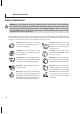
Safety Statements Safety Statements WARNING! The following safety precautions will increase the life of the Notebook PC. Follow all precautions and instructions. Except as described in this manual, refer all servicing to qualified personnel. Do not use damaged power cords, accessories, or other peripherals. Do not use strong solvents such as thinners, benzene, or other chemicals on or near the surface. Disconnect the AC power and remove the battery pack(s) before cleaning.
Safety Statements Transportation Precautions To prepare the Notebook PC for transport, you should turn it OFF and disconnect all external peripherals to prevent damage to the connectors. The hard disk drive’s head retracts when the power is turned OFF to prevent scratching of the hard disk surface during transport. Therefore, you should not transport the Notebook PC while the power is still ON.
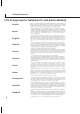
Safety Statements CTR 21 Approval (for Notebook PC with built-in Modem) Danish Dutch English Finnish French German Greek Italian Portuguese Spanish Swedish 6
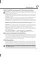
Safety Statements UL Safety Notices Required for UL 1459 covering telecommunications (telephone) equipment intended to be electrically connected to a telecommunication network that has an operating voltage to ground that does not exceed 200V peak, 300V peak-to-peak, and 105V rms, and installed or used in accordance with the National Electrical Code (NFPA 70).
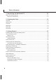
Table of Contents 1. Introducing the Notebook PC ................................................................ 11 About This User’s Manual ..................................................................................................... 12 Notes For This Manual ..................................................................................................... 12 2. Knowing the Parts .................................................................................. 13 Top Side .....................
Table of Contents 4. Using the Notebook PC ......................................................................... 35 Pointing Device ..................................................................................................................... 36 Using the Touchpad ......................................................................................................... 36 Touchpad Usage Illustrations ...........................................................................................
Processor & Hard Disk Drive Upgrades ................................................................................ 63 System Memory Expansion .................................................................................................. 63 Vehicle/Air & Vehicle-Only Power Adapters (Optional) ......................................................... 63 Securing Your Notebook PC (Optional) ................................................................................. 64 5. Configuring the BIOS ....
1.
Introducing the Notebook PC About This User’s Manual You are reading the Notebook PC User’s Manual. This User’s Manual provides information on the various components in the Notebook PC and how to use them. The following are major sections of this User’s Manuals: 1. Introducing the Notebook PC Introduces you to the Notebook PC and this User’s Manual. 2. Knowing the Parts Gives you information on the Notebook PC’s components. 3. Getting Started Gives you information on getting started with the Notebook PC.
2.
Knowing the Parts Top Side Refer to the diagram below to identify the components on the top side of the Notebook PC. Display Panel Microphone Power Switch / Instant Keys Keyboard Touchpad Touchpad Buttons Opening the Display Panel One spring-loaded latch on the front of the Notebook PC locks the display panel in the closed position when the Notebook PC is not in use. To open the display panel, push the button in with your thumb, remove your thumb, and then lift up the display panel with the same thumb.
Knowing the Parts Display Panel The display panel functions the same as a desktop monitor. The Notebook PC uses an active matrix TFT LCD, which provides excellent viewing like that of desktop monitors. Unlike desktop monitors, the LCD panel does not produce any radiation or flickering, so it is easier on the eyes. Display Panel Care The LCD screen is very delicate and requires careful handling.
Knowing the Parts Bottom Side Refer to the diagram below to identify the components on the bottom side of the Notebook PC. Air Vent & Fan Memory Compartment Name Card Holder Reset Button Battery Compartment Audio Speaker WARNING! The bottom of the Notebook PC can get very hot. Be careful when handling the Notebook PC while it is in operation or recently been in operation. High temperatures are normal during charging or operation.
Knowing the Parts The following describes the components on the bottom side of the Notebook PC as shown by the illustration on the previous page. Battery Compartment The battery compartment’s surface is actually combined with the battery pack in order to reduce thickness. When the battery is released, the compartment cover and battery pack will be seen as a single unit. The battery pack cannot be further disassembled and must be replaced as a single unit.
Knowing the Parts Left Side Refer to the diagram below to identify the components on the left side of the Notebook PC. DC Power Input Jack AI-Box Port PC Card (PCMCIA) Socket DC IN DC IN IEEE 1394 Port 2 USB Ports Fast IrDA Port 1394 DC Power Input Jack The supplied power adapter converts AC power to DC power for use with this jack. Power supplied through this jack supplies power to the Notebook PC and charges the internal battery pack.
Knowing the Parts Fast Infrared Port (IrDA) The fast infrared (IrDA) communication port allows convenient wireless data communication with infrared-equipped devices or computers up to 4 Mbits/sec. This allows easy wireless synchronization with PDAs or mobile phones and even wireless printing to printers. If your office supports IrDA networking, you can have wireless connection to a network anywhere provided there is a direct line of sight to an IrDA node.
Knowing the Parts Rear Side Refer to the diagram below to identify the components on the rear side of the Notebook PC. LAN Port (RJ-45) USB Port Modem Port (RJ-11) Air Vent & Fan External Monitor Port External Expansion Port Kensington® Lock Port K The following describes the components on the rear side of the Notebook PC as shown by the illustration above. Air Vent and Cooling Fan The cooling fan turns ON when the temperature rises past a set threshold.
Knowing the Parts External Expansion Port The External Expansion Port is for connection to an optional Portbar II or PortDock II to provide a docking solution to desktop peripherals and expansion options to various drive modules. More details given later. K Kensington® Lock Port The Kensington® lock port allows the Notebook PC to be secured using Kensington® compatible Notebook PC security products.
Knowing the Parts Front Side Refer to the diagram below to identify the components on the front side of the Notebook PC. Head-Out Mic-In Status Indicators Display Panel Latch Wireless LAN Indicator Microphone Jack (Mic-In) The mono microphone jack can be used to connect an external microphone or output signals from audio devices. Using this jack automatically disables the built-in microphone.
3.
Getting Started Using the Battery Pack Installing and Removing the Battery Pack Your Notebook PC may or may not have its battery pack installed. If your Notebook PC does not have its battery pack installed, there will be a large opening at the bottom of the Notebook PC. Use the following procedures to install or remove the battery pack. To install the battery pack: 1. Slide the Battery Lock to the unlock position L . 2. Insert the battery pack as shown. 3. Snap the battery pack into the Notebook PC 4.
Getting Started Charging the Battery Pack Before you use your Notebook PC on the road, you will have to charge the battery pack. The battery pack begins to charge as soon as the Notebook PC is connected to external power. Fully charge the battery pack before using it for the first time. A new battery pack must completely charge before the Notebook PC is disconnected from external power. When the battery power is low, the battery power LED will blink.
Getting Started Power Connection Your Notebook PC comes with a universal AC-DC adapter. That means that you may connect the power cord to any 110V-120V as well as 220V-240V outlets without setting switches or using power converters. Different countries may require that an adapter be used to connect the provided US-standard AC power cord to a different standard. Most hotels will provide universal outlets to support different power cords as well as voltages.
Getting Started Powering ON The Notebook PC The Notebook PC’s power-ON message appears on the screen followed by a short beep when you turn it ON. If necessary, you may adjust the brightness by using the hot keys. If you need to run the BIOS Setup to set or modify the system configuration, press [F2] upon bootup to enter the BIOS Setup. If you press [Tab] during the splash screen, standard boot information such as the BIOS version can be seen.
Getting Started Power Management - Stand By and Hibernate Power management settings can be found in the Windows control panel. The following shows the power options properties in Windows ME. You can define Stand By or Power Off for closing the display panel, pressing the power button, or activating sleep mode. Basically Stand by and Hibernate saves power when your Notebook PC is not in use by turning OFF certain components.
Getting Started Using the Keyboard Colored Hot Keys The following defines the colored hot keys on the Notebook PC’s keyboard. The colored commands can only be accessed by first pressing and holding the function key while pressing a key with a colored command. NOTE: The Hot Key locations on the function keys may vary depending on model but the functions should remain the same. Follow the icons instead of the function keys (F1, F5, F6, etc.
Getting Started Instant Launch Keys and Status Indicators Above the Keyboard 1 A Status Indicators Activity Indicator Indicates that the Notebook PC is accessing one or more storage device(s) such as the hard disk or optical storage drive. The light flashes proportional to the access time. 1 Number Lock Indicates that number lock [Num Lk] is activated when lighted. Number lock allows some of the keyboard letters to act as numbers for easier numeric data input.
Getting Started Power Gear The Power Gear button toggles power savings ON or OFF. When power savings is activated, CPU speed and LCD brightness will be decreased. Power Gear will decrease power consumption even more if used together with Intel SpeedStep. Power Gear works only in battery mode and Intel SpeedStep will work in battery or AC mode but requires manual configuration to work in AC mode.
Getting Started Microsoft Windows™ Keys There are two special Windows™ keys on the keyboard as described below. The key with the Windows™ Logo activates the Start menu located at the bottom left of the Windows™ desktop. The other key, that looks like a Windows™ menu with a small cursor, activates the properties menu and is equivalent to pressing the right mouse button on a Windows™ object.
Getting Started Keyboard as Cursors The keyboard can be used as cursors while Number Lock is ON or OFF in order to increase navigation ease while entering numeric data in spreadsheets or similar applications. and one of the cursor keys shown below. For example [Fn][8] for With Number Lock OFF, press up, [Fn][K] for down, [Fn][U] for left, and [Fn][O] for right. With Number Lock ON, use [Shift] and one of the cursor keys shown below.
4.
Using the Notebook PC Pointing Device The Notebook PC’s integrated touchpad pointing device is fully compatible with all two/three-button and scrolling knob PS/2 mice. The touchpad is pressure sensitive and contains no moving parts; therefore, mechanical failures can be avoided. A device driver is still required for working with some application software. See the Driver & Utility Guide for information on drivers and utilities for the touchpad.
Using the Notebook PC Clicking/Tapping - With the cursor over an item, press the left button or use your fingertip to touch the touchpad lightly, keeping your finger on the touchpad until the item is selected. The selected item will change color. The following 2 examples produce the same results.
Using the Notebook PC Dragging - Dragging means to pick up an item and place it anywhere on the screen you wish. You can move the cursor over the item you select, and while keeping the left button depressed, moving the cursor to the desired location, then release the button. Or, you can simply double-tap on the item and hold while dragging the item with your fingertip. The following 2 examples produce the same results.
Using the Notebook PC AiBox Portable Module Bay The external AiBox Portable Module Bay provides a convenient solution to connect external devices such as CD, DVD, CD-RW, DVD+CD-RW, or a second hard disk drive to the Notebook PC using a single cable. External devices can be easily interchanged in the AiBox. WARNING! AiBox now supports Plug & Play under Windows XP on this Notebook PC. When the power is ON, connect the AiBox and/or insert a module drive. The module drive will be automatically detected.
Using the Notebook PC Connecting the AiBox The AiBox connects to the AiBox port located on the left side of the Notebook PC.
Using the Notebook PC Optical Drive Module (Optional) NOTE: The terms “CD-ROM” or “CD” are mainly used in all documentation because of its wide familiarity, although “CD/DVD” should be more appropriate since this Notebook PC supports CD-ROM, CD-RW, and DVD-ROM optional modules. The CD-ROM (Compact Disc Read Only Memory) drive can support all the popular formats: Audio/ Music CDs; Photo CDs; MS-DOS MSCDEX Mode 1 / Mode 2; CD-ROM/XA; CD-I; and Video CDs.
Using the Notebook PC Inserting an optical disc 1. While the Notebook PC’s power is ON, press the drive’s eject button and the tray will eject out partially. 2. Gently pull on the drive’s front panel and slide the tray completely out. Be careful not to touch the CD drive lens and other mechanisms. Make sure there are no obstructions that may get jammed under the drive’s tray. 3. Hold the disc by the edge and face the disc’s printed side up.
Using the Notebook PC Using the CD-ROM Drive CD-ROM discs and equipment must be handled with care because of the precise mechanics involved. Keep in mind the important safety instructions from your CD suppliers. Unlike desktop CD-ROM drives, the Notebook PC uses a hub to hold the CD in place regardless of the angle. When inserting a CD, it is important that the CD be pressed onto the center hub or else the CD-ROM drive tray will scratch the CD.
Using the Notebook PC Software To meet customer requirements for a complete DVD solution, a software playback solution is provided. The provided software has been optimized for playback of MPEG2 (Motion Picture Experts Group specifications for data compression) encoded video clips as well as encrypted DVD movie titles. Decoding digital MPEG2 video is accomplished through software only, eliminating the need for expensive hardware.
Using the Notebook PC Regional Playback Information Playback of DVD movie titles involves decoding MPEG2 video, digital AC3 audio and decryption of CSS protected content. CSS (sometimes called copy guard) is the name given to the content protection scheme adopted by the motion picture industry to satisfy a need to protect against unlawful content duplication. Although the design rules imposed on CSS licensors are many, one rule that is most relevant is playback restrictions on regionalized content.
Using the Notebook PC Second Hard Disk Drive Module (Optional) The convenient design of the Notebook PC allows for the usage of a second hard disk drive in the modular bay. A second hard disk drive allows you to use it as a removable device, for installing dual operating systems, for additional data storage, or to store CDs. To use a second hard disk drive, you must be familiar with the following: • What to purchase and the contents of the kit.
Using the Notebook PC PortBar II Accessory (Optional) If you require a simple inexpensive docking solution, just use a PortBar to connect your desktop devices and then quickly connect or disconnect all the devices through a single easy-to-use connector. The PortBar’s Plug & Play feature allows it to be connected or disconnected while the Notebook PC is ON or OFF (hot-dockable). Except for the device connected to the serial port, other devices should function normally while hot-dockable.
Using the Notebook PC PortBar II Accessory (Cont’) Docking Solution For long-term use of the Notebook PC or if the Notebook PC is intended to be a desktop replacement computer, the PortBar provides a convenient docking solution. A desktop PS/2 mouse, PS/2 keyboard, monitor, printer, serial device, and Notebook PC power can all be connected to the PortBar.
Using the Notebook PC Optional External Connections Monitor Out Connection K Connecting an external monitor is just like on a standard desktop PC. Just plug in the VGA cable and its ready to use (some Notebook PC configurations may require additional display driver settings). You can view the Notebook PC display panel while simultaneously allowing others to view the external monitor. For large audiences, try connecting a computer video projector.
Using the Notebook PC Optional External Connections (Cont’) External Audio Connections The Notebook PC provides easy access for connecting a stereo headphone, mono microphone, and a stereo audio source just like on some personal tape recorders.
Using the Notebook PC Optional External Connections (Cont’) USB ports are provided on both the left and rear sides for connection to USB devices. External Keyboard Connection To allow easier data entry, you may connect any USB keyboard as shown here. DC IN 1394 K Connect to Rear Side Connect to Left Side External Mouse Connection A USB mouse can be easily connected to the Notebook PC. There is only one correct orientation with the USB symbol facing upwards.
Using the Notebook PC USB Floppy Disk Drive (Optional) The Notebook PC features an optional USB-interface disk drive that accepts a standard 1.44MB (or 720KB) 3.5-inch floppy diskette. The eject button is on the top edge of the floppy disk drive for easy access, unlike desktop PCs with the eject button on the bottom of the floppy disk drive. Floppy access activity can be monitored through the LED on the front of the floppy disk drive. Connection Connection is very easy because of USB technology.
Using the Notebook PC PC Card (PCMCIA) Socket The Notebook PC supports PC Cards (or sometimes referred to as PCMCIA cards) to allow expansion like PCI cards on desktop computers. This allows you to customize your Notebook PC to meet a wide range of application needs. The PCMCIA socket can interface with type I or type II PC cards. PC cards are about the size of a few stacked credit cards and have a 68-pin connector at one end.
Using the Notebook PC Inserting a PC Card (PCMCIA) 1. Insert the PC card with the connector side first. When the PC card is fully inserted, the PC card bay door can close normally without striking the PC card. 2. Carefully connect any cables or adapters needed by the PC card. Usually connectors can only be inserted in one orientation. Look for a sticker, icon, or marking on one side of the connector representing the top side. T R E S IN IS TH D N E Be sure the PC card is level when inserting.
Using the Notebook PC Modem and Network Connections The built-in modem and network model comes with both an RJ-11 and an RJ-45 port. RJ-11 telephone cables have two or four wires and are used to connect telephones to telephone outlets found in the walls of residential homes and some commercial buildings (some commercial buildings may have telephone wiring designed for dedicated phone systems that may not be compatible).
Using the Notebook PC Network Connection Connect a network cable, with RJ-45 connectors on each end, to the modem/network port on the Notebook PC and the other end to a hub or switch. For 100BASE-TX speeds, your network cable must be category 5 (not category 3) with twisted-pair wiring. If you plan on running the interface at 100Mbps, it must be connected to a 100BASE-TX hub (not a 100BASE-T4 hub). For 10Base-T, use category 3, 4, or 5 twisted-pair wiring.
Using the Notebook PC IR Wireless Communication The Notebook PC is equipped with a conveniently located Infrared (IR) Communication Port (see 2. Knowing the Parts for location). The IR port comes with IrDA (Infrared Data Association) Serial Infrared Data Link Version 1.1 compliance, that allows you to perform point-to-point wireless communications. You can use a FIR-specified application to transmit or receive data files with other systems equipped with an infrared port.
Using the Notebook PC CAUTION! Disable the infrared communication when you are not using the IR for long periods because the IR consumes a great deal of Windows resources which will decrease the Notebook PC’s performance. AC Power System The Notebook PC power is comprised of two parts, the power adapter and the battery power system. The power adapter converts AC power from a wall outlet to the DC power required by the Notebook PC. The battery pack consists of a set of battery cells housed together.
Using the Notebook PC Using Battery Power A fully-charged battery pack provides the Notebook PC a few hours of working power. But the actual figure varies depending on how you use the power saving features, your general work habits, the CPU, system memory size, and the size of the display panel. The “Battery Warning” beeps are automatically enabled in Windows ME and beeps once when down to 10% (configurable in Windows ME) power. The processor is also throttled down to decrease power use.
Using the Notebook PC Power Management Modes The Notebook PC has a number of automatic or adjustable power saving features that you can use to maximize battery life and lower Total Cost of Ownership (TCO). You can control some of these features through the Power menu in the BIOS Setup. ACPI power management settings are made through the operating system.
Using the Notebook PC Power Savings In addition to reducing the CPU clock, this mode puts devices including the LCD backlight in their lower active state. The Notebook PC enters Standby mode (low priority) when the system remains idle for a specified amount of time. The timeout can be set through BIOS setup (lower priority) and Windows power management (higher priority). To resume system operation, press any key.
Using the Notebook PC System Memory Expansion Additional memory is optional and not required to use the Notebook PC. Additional memory will increase application performance by decreasing hard disk access. This is more noticeable on newer software that require more and more system resources. The Notebook PC comes with some built-in memory. One standard 144-pin SO-DIMM (Small Outline Dual Inline Memory Module) socket is available for system memory expansion using common 3.3 Volt 133MHz SDRAM SO-DIMM modules.
Using the Notebook PC Vehicle/Air & Vehicle-Only Power Adapters (Optional) The main purpose of the vehicle/air or vehicle-only power adapters is to provide a source of power for using the Notebook PC and/or charging the Notebook PC’s battery from while in transit when no AC power is available. These products are essential tools for today’s mobile professional. Your purchase will enhance the power, performance, and versatility of your portable computer while traveling in the air, on the road, or on the sea.
Using the Notebook PC Securing Your Notebook PC (Optional) For system and hard disk drive security, see BIOS setup “Security”. A third party lock such as the ones by Kensington® can be used to secure your Notebook PC physically to an unmovable object. The cable wraps around an object and the “T” shaped end inserts into the Kensington® lock port as shown in this illustration and a key or combination dial is used to secure the lock in place.
5.
Configuring the BIOS BIOS Setup Program This Notebook PC supports a programmable EEPROM that stores the BIOS software and can be updated using the provided flash memory writer utility. This Section will guide you through the BIOS setup program by providing clear explanations for all the options. A default configuration has already been set. If you are either installing new devices or expanding main memory, you will need to enter the BIOS Setup to reconfigure your Notebook PC.
Configuring the BIOS Updating your BIOS This Notebook PC supports an easy-to-use BIOS update software called “WINFLASH” which is installed through the provided support CD. If you need help installing or using “WINFLASH”, refer to the “Driver & Utility Manual”. BIOS Menu Bar The top of the screen has a menu bar with the following selections: MAIN Use this menu to make changes to the basic system configuration.
Configuring the BIOS General Help In addition to the Item Specific Help window, the BIOS setup program also provides a General Help screen. This screen can be called up from any menu by simply pressing [F1] or the [Alt] + [H] combination. The General Help screen lists the legend keys with their corresponding alternates and functions. Scroll Bar When a scroll bar appears to the right of a help window, it indicates that there is more information to be displayed that will not fit in the window.
Configuring the BIOS Main Menu When the Setup program is accessed, the main menu screen appears as shown: Item Specific Help System Time System Date [17:15:00] [11/19/2001] Primary Master Primary Slave Secondary Master Secondary Slave [IC25N030ATDA04-0] [Auto] [Auto] [Auto] Video Display Device Installed Memory [LCD & CRT] 128 MB to select field; <+>,<-> to change value.
Configuring the BIOS Video Display Device [LCD & CRT] This field allows you to select and enable video display devices, such as an LCD panel, an external CRT/LCD monitor, or both. The configuration options are: [LCD & CRT] [LCD] [CRT] Installed Memory [128 MB] (display field) This field displays the amount of extended memory as detected by the system. Unfortunately, this will not tell you how much is onboard and how much is added to the SO-DIMM socket.
Configuring the BIOS Primary Master (sub-menu) This field is used to configure the primary IDE drive installed in the system. To configure a hard disk drive, select this sub-menu from the Main menu and press the Enter key to enter this sub-menu.
Configuring the BIOS Cylinders [ ] This field configures the number of cylinders. Refer to your drive documentation to determine the correct value to enter into this field. NOTE: To make changes to this field, the Type field must be set to User Type HDD and “Translation Method” must be set to Manual. Heads [ ] This field configures the number of read/write heads. Refer to your drive documentation to determine the correct value to enter into this field.
Configuring the BIOS Ultra DMA Mode [ ] This field auto detects Ultra DMA capability (for improved transfer speeds and data integrity) for compatible IDE (Integrated Disk Electronics) devices. Set to Disable to suppress Ultra DMA capability. NOTE: To make changes to this field, the Type field must be set to User Type HDD. The configuration options are: [0] [1] [2] [3] [4] [5] [Disabled].
Configuring the BIOS Advanced Menu Selecting Advanced from the main menu bar display the Advanced menu as shown below. Item Specific Help I/O Device Configuration Internal Pointing Device Quick Power On Self Test [Enabled] [Enabled] to go to the sub-menu. >I/O Device Configuration (described on next page) Pressing [Enter] when this field is highlighted calls up a sub-menu for configuring the Notebook PC’s serial and parallel ports.
Configuring the BIOS I/O Device Configuration (sub-menu) I/O Device Configuration IR Port Mode DMA Channel [2F8H/IRQ3] [FIR] [1] Parallel Port: Mode: ECP DMA Select: [378H/IRQ7] [ECP+EPP] [3] Item Specific Help to select the I/O Address & IRQ for Infrared. NOTE: The presence of sub-items in this menu is dependent on certain relevant settings.
Configuring the BIOS Parallel Port: [378H/IRQ7] This field allows you to configure the Notebook PC parallel port. The configuration options are: [Disabled] [378H/IRQ7] [278H/IRQ5] Mode: [ECP+EPP] The Mode field allows you to configure the Notebook PC parallel port transmission mode. The configuration options are: [Normal] [EPP] [ECP] [ECP+EPP] EPP Mode: When the EPP mode is selected, the standard and bidirectional modes are also available. The EPP operates on a two phase cycle.
Configuring the BIOS Security Menu The Notebook PC’s advanced system of security allows you to set a password to prevent unauthorized access to system resources, data, and the BIOS Setup Program. This Section covers each parameter of the Security Setup. Selecting Security from the menu bar displays the following menu: Item Specific Help System Password Password on boot [Enter] [Disabled] Hard disk Password [Enter] Supervisor password controls full access.
Configuring the BIOS System Password [Enter] The system password protects the BIOS settings. When “Enabled”, you will be prompted for a password after you press [F2] to enter BIOS setup. To Enable: Select “Enter” and press [Enter], type a password and press [Enter], type the same password again and press [Enter] to confirm. (You can type up to eight alphanumeric characters. Symbols and other keys are ignored.) To Disable: Select “Set” and press [Enter] without entering a password.
Configuring the BIOS Power Menu The power management settings are controlled by the operating system. This menu only has one function as follows: Item Specific Help LCD auto power saving [Enabled] Start Battery Refreshing to select the Power Saving Mode. You can select ‘User Define” to go to the Suspend Mode entry below. LCD Auto Power Saving [Enabled] Enabling this item will decrease the LCD brightness when the AC power is not connected in order to conserve battery power.
Configuring the BIOS Boot Menu The Boot menu allows the user to specify the order in which the Notebook PC is to check for a device to boot the system. To make changes, select Boot from the menu bar and the following screen appears: Item Specific Help 1. Removable Device 2. IDE Hard Drive 3. ATAPI CD-ROM 4. Other Boot Device Onboard LAN Boot ROM [USB FDD] [IC25N030ATDA04-0] [None] [INT18 Device (Network)] [Disabled] Boot Sequence: to select the device.
Configuring the BIOS Exit Menu Once you have made all of your selections from the various menus in the Setup program, you should save your changes and exit Setup. Select Exit from the menu bar to display the following menu: Item Specific Help Exit Saving Changes Exit Discarding Changes Load Setup Defaults Discard Changes Save Changes Exit setup utility and save your changes to CMOS. NOTE: Pressing the [Esc] key does not exit this menu.
Configuring the BIOS Load Setup Defaults This option allows you to load the default values for each of the parameters on the Setup menus. When this option is selected or if [F9] is pressed, a confirmation is requested. Select Yes to load default values programmed into the BIOS file (the default values may change from one BIOS version to another). You can now select Exit Saving Changes or make other changes before saving the values to the EEPROM.
Appendix Appendix Internal Modem Compliancy Glossary Index Owner Information A
Appendix Internal Modem Compliancy The Notebook PC with internal modem model complies with JATE (Japan), FCC (US, Canada, Korea, Taiwan), and CTR21. The internal modem has been approved in accordance with Council Decision 98/ 482/EC for pan-European single terminal connection to the public switched telephone network (PSTN).
Appendix A This table shows the countries currently under the CTR21 standard.
Appendix Glossary ACPI (Advanced Configuration and Power Management Interface) Modern standard for reducing power usage in computers. APM (Advanced Power Management) Modern standard for reducing power usage in computers. AWG (American Wire Gauge) Gauge Diam Area R I@3A/mm2 Gauge Diam Area R I@3A/mm2 AWG (mm) (mm2) (ohm/km) (mA) AWG (mm) (mm2) (ohm/km) (mA) 46 44 0.04 0.05 0.0013 0.0020 13700 8750 3.8 6 24 0.50 0.55 0.20 0.24 87.5 72.3 588 715 42 0.06 0.0028 6070 9 0.
Appendix A BIOS (Basic Input/Output System) BIOS is a set of routines that affect how the computer transfers data between computer components, such as memory, disks, and the display adapter. The BIOS instructions are built into the computer’s read-only memory. BIOS parameters can be configured by the user through the BIOS Setup program. The BIOS can be updated using the provided utility to copy a new BIOS file into the EEPROM. Bit (Binary Digit) Represents the smallest unit of data used by the computer.
Appendix IDE (Integrated Drive Electronics) IDE devices integrate the drive control circuitry directly on the drive itself, eliminating the need for a separate adapter card (in the case for SCSI devices). UltraDMA/66 or 100 IDE devices can achieve up to 33MB/Sec transfer. IEEE1394 Also known as iLINK (Sony) or FireWire (Apple). IEEE1394 is a high speed serial bus like SCSI but has simple connections and hot-plugging capabilities like USB.
Appendix A POST (Power On Self Test) When you turn on the computer, it will first run through the POST, a series of software-controlled diagnostic tests. The POST checks system memory, the motherboard circuitry, the display, the keyboard, the diskette drive, and other I/O devices. PS/2 Port PS/2 ports are based on IBM Micro Channel Architecture. This type of architecture transfers data through a 16-bit or 32-bit bus. A PS/2 mouse and/or keyboard may be used on ATX motherboards.
Appendix 90
Appendix A Index A C AC Power System 59 AiBox Portable Module 39 APM and ACPI 60 Canadian Department of Communications 2 Capital Lock 30 CardBus 53 CDRH Regulations 3 Colored Hot Keys 29 Cooling Fan 20 CTR 21 Approval 6 B Battery Pack 24 Battery Power System 59 BIOS Advanced Menu 74 BIOS Legend Bar 67 BIOS Menu Bar 67 BIOS Setup Program 66 Boot Menu 80 Boot Sequence 80 Cylinders 72 Discard Changes 82 DMA Channel 74, 76 Exit Discarding Changes 81 Exit Menu 81 Exit Saving Changes 81 Heads 72 I/O Device
Appendix K R Keyboard 15 L Region Definitions 45 Regional Playback Information 45 Restarting or Rebooting 28 Laser Safety 41 S M Securing Your Notebook PC 64 Status Indicators 30 Suspend Mode 60, 89 System Memory Expansion 63 Macrovision Notice 3 Microphone Jack 22 Microsoft Windows™ Keys 32 Modem and Network Connections 55 Modem Port 20 Monitor Out Connection 49 Mouse or Keyboard Connection 51 Network Connection 56 Nordic Cautions 3 Numeric Keypad, alternate 32 Table of Contents 9 Thermal Power
Appendix A 93
Appendix Owner Information This page is provided for recording information concerning your Notebook PC for future reference or for technical support. Keep this User’s Manual in a secured location if passwords are filled out.