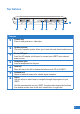
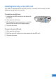
Top features 7 1 3 5 6 Features 1 Camera key Press to take pictures or video clips. Speaker system The built-in speaker system allows you to hear rich and vibrant audio/sound. 3 Power (DC) port Insert the AC adapter into this port to connect your UMPC to an external power source. Headphone jack Insert a headphone into this port. 5 Hold key Move this key to the left to disable the buttons and LCD of th UMPC.
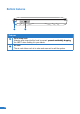
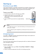
Bottom features 1 Features 1818 1 Wrist strap hook Attach a wrist strap into this hook to prevent prevent accidentally dropping the UMPC when holding it in your hands. Air vent The air vent allows cool air to enter and warm air to exit the system.
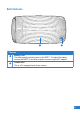
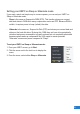
Back features 1 Features 1 Battery Pack The battery pack provides power to the UMPC. To charge the battery, connect the UMPC to an external power source using the AC adapter. Camera lens This is a 2.0 megapixel auto focus camera.
Getting your UMPC ready Before using the UMPC for the first time, ensure that the battery pack is fully charged. Charging the battery pack Your UMPC package comes with a universal AC-DC adapter which charges the battery pack, and in turn supplies power to your UMPC. You may connect the adapter to a 100120V or 220V-240V outlet without setting switches or using power converters.
Installing/removing a microSD card Your UMPC is equipped with a microSD card slot. A microSD card provides you with additional storage space for your files. To install the microSD card: 1. Locate the microSD card slot at the left side of the UMPC. 2. Lift to open the slot cover. 3. With the golden fingers facing down, insert the microSD into the slot until it snaps properly. 4. Close the slot cover. microSD card slot To remove the microSD card: 1. Lift to open the slot cover. 2.
Starting up Powering on your UMPC Like a regular desktop PC, your UMPC automatically runs a series of diagnostic tests called Power-On Self Test (POST) upon turning it on. After POST is completed, your UMPC boots up, then its Windows® operating system starts automatically. To power on your UMPC: 1. Locate the power switch at the left side of your UMPC. 2. Press the switch down to turn on the UMPC. The UMPC boots up, then the operating system starts automatically. 3.
Setting your UMPC on Sleep or Hibernate mode If you want a quick and simple way to conserve power, you can set your UMPC on Sleep or Hibernate mode: • Sleep is the same as Suspend-to-RAM (STR). This function stores your current data and status in RAM while many components are turned OFF. Because RAM is volatile, it requires power to keep (refresh) the data. • Hibernate is the same as Suspend-to-Disk (STD) and stores your current data and status on the hard disk drive.
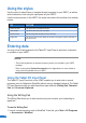
Chapter Using your UMPC • Using the stylus • Entering data • Calibrating the screen • Securing your UMPC 5 5
Using the stylus Use the stylus to select items or navigate through programs on your UMPC, as well as write characters or text using the input panel on your UMPC. Like the mouse pointer on the UMPC, the stylus also mimics the functions of a desktop mouse. TO DO THIS Select an item Tap the screen once with the stylus. Run an item Tap the screen twice with the stylus. Move an item Tap and drag with the stylus to move the item. Right-click Tap and hold the screen.
2. 3. 4. 5. 6. Tap the screen with the stylus. The Tablet PC Input Panel icon appears. Tap . The Tablet PC Input Panel appears. . The Writing Pad appears. On the input panel, tap Using your stylus, write on the screen as you would write on a piece of paper. When done, tap Insert. The text you wrote appears on the Wordpad. NOTE: Ensure that you write legibly. Using the Character Pad The Character Pad converts each of your handwritten text, symbol, or character into typed text one at a time.
Calibrating the screen Calibrating the screen ensures that the touchscreen feature of the UMPC works properly when tapped with the stylus or with your finger. 1. Launch Control Panel from Windows Start. 3. Click the Calibrate button on the “General” page. 8 8 2. Double click Tablet PC Settings icon. 4. Carefully tap the center of each cross hair that appears near each corner to complete the calibration process.
Securing your UMPC Enrolling your fingerprint data The fingerprint sensor on the UMPC makes your device more secure from unauthorized access. With the fingerprint sensor, you can enter your fingerprint data as your authentication mechanism for your UMPC. 1. This wizard will automatically start when TPM is enabled in BIOS after setting security passwords. Click Next to continue. 2. Select “Fingerprints” and click Next. 3. Select a finger on the diagram, and swipe that finger on the fingerprint sensor.
5. Click Finish when done. You need to configure the Security Protect Manager to enable fingerprint settings. Configuring the Security Protect Manager The Security Protect Manager enables you to use your registered credentials, such as your fingerprint data, to log on to Windows and other applications. To configure the Security Protect Manager: 1. Right-click the icon on the taskbar and select “Settings and Options”. 3030 2. Select “General Options” and “Single Sign On” and configure your preferences.
Chapter 3 Connections • Network Connection • Wireless LAN Connection • Windows® Wireless Network Connection • ASUS Wireless LAN • Bluetooth Wireless Connection 3131
Network Connection Connect a network cable, with RJ-45 connectors on each end, to the modem/network port on the Notebook PC and the other end to a hub or switch. For 100 BASE-TX / 1000 BASE-T speeds, your network cable must be category 5 or better (not category 3) with twisted-pair wiring. If you plan on running the interface at 100/1000Mbps, it must be connected to a 100 BASE-TX / 1000 BASE-T hub (not a BASE-T4 hub). For 10Base-T, use category 3, 4, or 5 twisted-pair wiring.
Wireless LAN Connection (on selected models) The optional built-in wireless LAN is a compact easy-to-use wireless Ethernet adapter. Implementing the IEEE 802.11 standard for wireless LAN (WLAN), the optional builtin wireless LAN is capable of fast data transmission rates using Direct Sequence Spread Spectrum (DSSS) and Orthogonal Frequency Division Multiplexing (OFDM) technologies on 2.4GHz/5GHz frequencies. The optional built-in wireless LAN is backward compatible with the earlier IEEE 802.
Windows Wireless Network Connection Connecting to a network (Vista) 1. Press [WIRELESS] switch repeatedly until Wireless LAN ON or WLAN & Bluetooth ON is shown. 3 3 1b. Or double click the Wireless Console icon on the taskbar and select either the 1st icon to activate both Wireless & Bluetooth, or select the 2nd icon for Wireless activation only. 2. You should see the “Not Connected” network icon. 3. Right click on the WLAN icon and select Connect to a network. 4.
Connecting to a network (XP) Using Windows XP wireless settings require that you select this option in the ASUS WLAN Control Center. 1. Press [WIRELESS] switch repeatedly until Wireless LAN ON or WLAN & Bluetooth ON is shown. 1b. Or double click the Wireless Console icon on the taskbar and click on the 1st icon to activate both Wireless & Bluetooth, or select the 2nd icon for Wireless activation only. 2. Double click the WLAN icon on the taskbar. 3.
ASUS Wireless LAN (on selected models) Connecting to a network Using ASUS wireless settings require that you select this option in the ASUS WLAN Control Center. 1. Press [WIRELESS] switch repeatedly until Wireless LAN ON or WLAN & Bluetooth ON is shown. 1b. Or double click the Wireless Console icon on the taskbar and click on the 1st icon to activate both Wireless & Bluetooth, or select the 2nd icon for Wireless activation only. 2.
6. Click the Encryption tab to configure the Network Authentication mode and Password. 7. The Status tab will show connection status and details. Note: Click “Save Configuration” and “Save” to remember settings for this network.
Bluetooth Wireless Connection (on selected models) Notebook PCs with Bluetooth technology eliminates the need for cables for connecting Bluetooth-enabled devices. Examples of Bluetooth-enabled devices may be Notebook PCs, Desktop PCs, mobile phones, and PDAs. Note: If your Notebook PC did not come with built-in Bluetooth, you need to connect a USB or ExpressCard Bluetooth module in order to use Bluetooth. Bluetooth-enabled mobile phones You can wireless connect to your mobile phone.
2. Select Add a Bluetooth Device on the taskbar men. 2b. Or Launch Bluetooth Devices from the Windows Control Panel.
0 0
Appendices Appendices • Optional Accessories • Optional Connections • Glossary • Notices • ASUS Contact information 1 1
Optional Accessories These items, if desired, come as optional items to complement your UMPC. Foldable USB Keyboard Mini-USB Port Slide latch to open. LOCK UNLOCK PrtSc F1 F2 F3 F4 F5 F6 F7 F8 F9 F10 F1 F11 F12 F1 SysRq Pause Break PgUp Home PgDn End Slide latch on the top to lock the keyboard in the open position. Extend: Pull the USB connectors apart (not fully) to extend the mini-USB cable. (Note: If you pull too much, it will retract.
More Optional Accessories These items, if desired, come as optional items to complement your UMPC. USB Hub (Optional) Attaching an optional USB hub will increase your USB ports and allow you to quickly connect or disconnect many USB peripherals through a single cable. USB Flash Memory Disk A USB flash memory disk is an optional item that can replace the 1.44MB floppy disk and provide storage up to several hundred megabytes, higher transfer speeds, and greater durability.
Optional Connections These items, if desired, may be purchased from third-parties. Printer Connection One or more USB printers can be simultaneously used on any USB port or USB hub. Bluetooth Mouse Setup (optional) This process can be used to add most Bluetooth devices in Windows operating system. 1. Press [WIRELESS] switch repeatedly until Bluetooth ON or WLAN & Bluetooth ON is shown. 1b.
ESET OFF ON 4. Click Next when the Bluetooth mouse is ready. R 2c. If launched from the Control Panel, click Add from this screen. 3. Prepare the Bluetooth mouse. • Install two “AA” batteries. • Turn ON the power switch on the bottom of the mouse. The bottom sensor should glow red. • Push the “RESET” button on the bottom of the Bluetooth mouse. 5. A list of nearby Bluetooth devices will be shown. Select the Bluetooth mouse and click Next.
6. Select “Don’t use a passkey” and click Next. 7. Wait while the Bluetooth mouse is being added. 8. Click Finish when adding is complete. 9. You will see your device in the window. You can also add or remove Bluetooth devices here. NOTE: “RESET” may be necessary after changing batteries. Repeat steps if necessary.
Operating System and Software This Notebook PC may offer (depending on territory) its customers the choice of a pre-installed Microsoft Windows operating system. The choices and languages will depend on the territory. The levels of hardware and software support may vary depending on the installed operating system. The stability and compatibility of other operating systems cannot be guaranteed.
Glossary ACPI (Advanced Configuration and Power Management Interface) Modern standard for reducing power usage in computers. APM (Advanced Power Management) Modern standard for reducing power usage in computers. AWG (American Wire Gauge) NOTE: This table is for general reference only and should not be used as a source of the American Wire Gauge standard as this table may not be current or complete. Gauge AWG 33 32 30 29 27 26 25 Diam (mm) 0.18 0.19 0.20 0.25 0.30 0.35 0.40 0.45 Area (mm ) 0.026 0.028 0.
ON your computer. “Reboot” means to restart your computer. When using Windows 95 or later, selecting “Restart” from “Start | Shut Down...” will reboot your computer. Bluetooth (on selected models) Bluetooth is a short-range wireless technology that lets you connect computers, mobile phones, and handheld devices to each other and to the Internet. Bluetooth technology eliminates the ned for the cables that connect devices together. Bluetooth-enabled devices connect wirelessly within a 10 m range.
Twisted-Pair Cable The cable used to connect the Ethernet card to a host (generally a Hub or Switch) is called a straight-through Twisted Pair Ethernet (TPE). The end connectors are called RJ-45 connectors, which are not compatible with RJ-11 telephone connectors. If connecting two computers together without a hub in between, a crossover twisted-pair is required. UltraDMA/66 or 100 UltraDMA/66 or 100 are new specifications to improve IDE transfer rates.
Notices Federal Communications Commission Statement This device complies with FCC Rules Part 15. Operation is subject to the following two conditions: • This device may not cause harmful interference, and • This device must accept any interference received, including interference that may cause undesired operation. This equipment has been tested and found to comply with the limits for a class B digital device, pursuant to Part 15 of the Federal Communications Commission (FCC) rules.
FCC RF Radiation Exposure Statement This equipment complies with FCC RF radiation exposure limits set forth for an uncontrolled environment. This equipment must not be co-located or operating in conjunction with any other antenna or transmitter. FCC Caution: Any changes or modifications not expressly approved by the party responsible for compliance could void the user’s authority to operate this equipment. “The manufacture declares that this device is limited to Channels 1 through 11 in the 2.
CE Mark Warning This is a Class B product, in a domestic environment, this product may cause radio interference, in which case the user may be required to take adequate measures. IC Radiation Exposure Statement for Canada This equipment complies with IC radiation exposure limits set forth for an uncontrolled environment. To maintain compliance with IC RF exposure compliance requirements, please avoid direct contact to the transmitting antenna during transmitting.
There are few possibilities for outdoor use: On private property or on the private property of public persons, use is subject to a preliminary authorization procedure by the Ministry of Defense, with maximum authorized power of 100mW in the 2446.5– 2483.5 MHz band. Use outdoors on public property is not permitted. In the departments listed below, for the entire 2.4 GHz band: • Maximum authorized power indoors is 100mW • Maximum authorized power outdoors is 10mW Departments in which the use of the 2400–2483.
UL Safety Notices Required for UL 1459 covering telecommunications (telephone) equipment intended to be electrically connected to a telecommunication network that has an operating voltage to ground that does not exceed 200V peak, 300V peak-to-peak, and 105V rms, and installed or used in accordance with the National Electrical Code (NFPA 70).
Nordic Lithium Cautions (for lithium-ion batteries) CAUTION! Danger of explosion if battery is incorrectly replaced. Replace only with the same or equivalent type recommended by the manufacturer. Dispose of used batteries according to the manufacturer’s instructions. (English) ATTENZIONE! Rischio di esplosione della batteria se sostituita in modo errato. Sostituire la batteria con un una di tipo uguale o equivalente consigliata dalla fabbrica. Non disperdere le batterie nell’ambiente.
ASUS Contact information ASUSTeK COMPUTER INC. (AsiaPacific) Address Website 15 Li-Te Road, Peitou, Taipei, Taiwan 11259 www.asus.com.tw Technical Support Telephone Support Fax Software download +886228943447 +886228907698 support.asus.com* ASUS COMPUTER INTERNATIONAL (America) Address Telephone Fax Website Software download 44370 Nobel Drive, Fremont, CA 94538, USA +15029550883 +15029338713 usa.asus.com support.asus.
5858