ASUS WLAN mini-PCI card WL-120 User Manual
Copyright Information No part of this manual, including the products and software described in it, may be reproduced, transmitted, transcribed, stored in a retrieval system, or translated into any language in any form or by any means, except documentation kept by the purchaser for backup purposes, without the express written permission of ASUSTeK COMPUTER INC. (“ASUS”).
Copyright Information ASUSTeK COMPUTER INC. (Asia-Pacific) Address: General Tel: General Fax: General Email: 150 Li-Te Road, Peitou, Taipei, Taiwan 112 +886-2-2894-3447 +886-2-2894-3449 info@asus.com.tw Technical Support MB/Others (Tel): +886-2-2890-7121 (English) Notebook (Tel): +886-2-2890-7122 (English) Desktop/Server: +886-2-2890-7123 (English) Support Fax: +886-2-2890-7698 Support Email: tsd@asus.com.tw Web Site: www.asus.com.
Quick Start Guide Chapter 1 Welcome The ASUS WLAN mini-PCI card is designed to be fully compliant with the IEEE 802.11b wireless local area network (Wireless LAN) standard. The ASUS WLAN mini-PCI card comes with two antenna connectors, which are individually connected to the built-in antennas in your notebook. The two antennas allow your notebook to have the best communication when you are enjoying the wireless link.
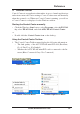
Quick Start Guide Installing the WLAN mini-PCI card Utilities After you have installed the WLAN mini-PCI card driver, you can install WLAN mini-PCI card utilities. Refer to the User's manual for detailed information. 1. Insert the ASUS WLAN mini-PCI card support CD and an autorun menu will appear. If your autorun is disabled, double click SETUP.EXE in the root directory of the support CD. 2. From the autorun menu, click Install ASUS WLAN mini-PCI card Utilities. 3.
Statement This device is intended only for OEM integrators under the following conditions: 1. The antenna must be installed such that 20 cm is maintained between the antenna and users. 2. The transmitter module may not be co-located with any other transmitter or antenna. 3. For laptop installations, the antenna must be installed to ensure that the proper spacing is maintained in the event the device is used in held-onlap positions (i.e.
Statement Manual Information for End Users: The end user must not have manual instructions to remove or install the device. The user manual for end users must include the following information in a prominent location "IMPORTANT NOTE: To comply with FCC RF exposure compliance requirements, the antenna used for this transmitter must be installed to provide a separation distance of at least 20 cm from all persons and must not be co-located or operating in conjunction with any other antenna or transmitter.
Reference Software Reference 1. Overview • • • • • Control Center – Makes it easy to launch applications and activate network location settings. Wireless Settings – Allows users to control the ASUS WLAN mini-PCI card. Mobile Manager – A convenient tool to setup and manage network location settings. Site Monitor – Measures the signal-to-noise (SNR) values of all wireless networks.
Reference 2. Windows XP Wireless Options The wireless options shown below is only available for Windows XP. The first time you run the Control Center utility, it will automatically show. Select one of the radio buttons to decide your Windows XP wireless networking environment. Only use XP wireless function – Only use Windows XP wireless network settings to configure the ASUS WLAN mini-PCI card.
Reference 3. Control Center Control Center is an application that makes it easy to launch applications and activate network location settings. Control Center starts automatically when the system boots. Whenever Control Center is running, you will see a Control Center icon displayed on the Windows taskbar. Starting the Control Center manually • Click the Windows Start button, select Programs, select ASUS Utility, select WLAN Card, and click ASUS WLAN Control Center.
Reference Wireless Status Icons (on the taskbar) Excellent link quality and connected to Internet (Infrastructure) Good link quality and connected to Internet (Infrastructure) Fair link quality and connected to Internet (Infrastructure) Poor link quality and connected to Internet (Infrastructure) Not linked but connected to Internet (Infrastructure) Excellent link quality but not connected to Internet (Infrastructure) Good link quality but not connected to Internet (Infrastructure) Chapter 3 Fair link qual
Reference 3. Left-clicking the taskbar icon shows the following menu: • Wireless Radio On – Turns the wireless radio ON. • Wireless Radio Off – Turns the wireless radio OFF. • Search and Join – View the properties of available Access Points within range. • Wireless Option (Windows XP only) – Sets your Windows XP wireless networking environment. 4. Double-clicking the taskbar icon: • Launches the Wireless Settings application.
Reference More than one ASUS WLAN Card If you have more than one ASUS WLAN Card. You will be given a device selection window when you launch the “Wireless Settings” utility. Chapter 3 4.1 Status - Status Tab You can view the information about the ASUS WLAN mini-PCI card from the general menu. These fields are blank if the ASUS WLAN mini-PCI card does not exist.
Reference Association State Shows the ASUS WLAN mini-PCI card association status as follows: Connected – The station is now associated with one wireless LAN device. Also, indicates the MAC address of this device. Scanning... – The station is now attempting to authenticate and associate with the desired Access Point. Disconnected – If the link is connected and no beacon received, then the set adapter is no longer connected. INT_TEST_FAIL – Interrupt test failed. NOT_AVAILABLE – Cannot get PC Card status.
Reference Button Enable Radio/Disable Radio – You can click the Disable Radio button to turn OFF the wireless radio. When you click this button, the Radio State field indicates that the radio has been turned OFF and the remaining fields in this window display either a “0” or “Not Applicable”. Click this button again to turn the radio back ON. Rescan – Force the radio to rescan all available channels.
Reference 4.2 Status - Connection Tab Chapter 3 You can view the current link statistics about the ASUS WLAN mini-PCI card. These statistics are updated once per second and are valid only if the ASUS WLAN mini-PCI card exists. Throughput Transmitted – The number of bytes in frames that were transmitted. Received – The number of bytes in frames that were received. Frame Error Transmitted – The number of frames that were not successfully transmitted.
Reference 4.3 Status - IP Config Tab IP Config tab shows all the current network configuration information for the ASUS WLAN mini-PCI card. Use it to verify your network settings. IP CONFIG will display all the current TCP/IP configuration values including the IP address, subnet mask, default gateway and Windows Internet Naming Service (WINS) and DNS configuration. Chapter 3 Button IP Release - Releases the DHCP IP address for the ASUS WLAN mini-PCI card.
Reference 4.4 Config - Basic Tab Chapter 3 Lets you can change the ASUS WLAN mini-PCI card configurations without rebooting your computer. Network Type Infrastructure – Select the Infrastructure mode to establish a connection with an Access Point. Your computer is able to access wireless LAN and wired LAN (Ethernet), via an associated access point. The Channel field turns to “Auto” when “Infrastructure” is selected.
Reference SSID Use the SSID filed to configure the SSID for the ASUS WLAN mini-PCI card. You can enter a new SSID or select one from the drop-down list box. SSID stands for “Service Set Identifier”, which is a string used to identify a wireless LAN. You will only be able to connect Access Points which has the same SSID as the one you set. Use different SSIDs to segment the wireless LAN and increase security.
Reference Chapter 3 Other WEP - Click on this to show the "Encryption" page. Advanced - Click on this to show the "Advanced" tab. In most cases, the default values do not have to be changed. Troubleshooting. - Click on this to show the "Troubleshooting" utility.
Reference 4.5 Config - Encryption Tab Lets you configure the ASUS WLAN mini-PCI card encryption settings. For data confidentiality in a wireless environment, IEEE 802.11 specifies a Wired Equivalent Privacy (WEP) algorithm to offer transmission privacy similar to wired network. The WEP uses keys to encrypt transmitted data packets and decrypt received data packets. The encryption process can scramble frame bits to avoid disclosure to others.
Reference Key Format You can enter the WEP Key as Hexadecimal digits (0~9, a~f, and A~F), or as ASCII characters, based on the state of the Key Format. Key Length For 64 bits encryption, each Key contains exactly 10 hex digits, or 5 ASCII characters. For 128 bits encryption, each Key contains exactly 26 hex digits, or 13 ASCII characters. Chapter 3 Two ways to assign WEP keys Manual Assignment – When you click this button, the cursor appears in the field for Key 1.
Reference 64/128bits versus 40/104bits You may be confused about configuring WEP encryption, especially when using multiple wireless LAN products from different vendors. There are two levels of WEP Encryption: 64 bits and 128 bits. First, 64 bit WEP and 40 bit WEP are the same encryption method and can interoperate in the wireless network. This lower level of WEP encryption uses a 40 bit (10 Hex character) as a “secret key” (set by user), and a 24 bit “Initialization Vector” (not under user control).
Reference 4.6 Config - Advanced Tab Chapter 3 Advanced tab provides some additional settings for the ASUS WLAN mini-PCI card. The “Advanced” tab is hidden until you click Advanced on the Config - Basic page. NOTE: This page is for advanced users. Do not change these settings if you do not fully understand these items. RTS Threshold Defines the size of packets that the station uses for RTS/CTS handshake boundary.
Reference Authentication Algorithm Because there is no precise bound in wireless LANs, it needs to be implemented in another mechanism to provide a higher level of security. That is where Authentication services come in. If a mutual authentication relationship has not been established between the ASUS WLAN mini-PCI card(s) and the Access Point(s), an association cannot be established.
Reference 4.7 Survey - Site Survey Tab • • • • • • • BSSID – View the IEEE MAC addresses of the available networks. SSID – View the SSID (service set identification) within available networks. CH – View the direct-sequence channel used by each network. S (dBm) – Signal field to view the strength of the signal transmitted by each network. This information is helpful in determining which network you should be associated to. The value is then normalized to a dBm value.
Reference 4.8 About - Version Info Tab Click about to view version information. The version under the copyright is the utility version. The version information field includes driver, hardware, and firmware versions.
Reference 4.9 Link Status ASUS WLAN mini-PCI card connection quality icon appears on the left of the ASUS WLAN Card Settings. Use the icon to view the current signal quality of the adapter. Excellent Link Quality (Infrastructure) Good Link Quality (Infrastructure) Fair Link Quality (Infrastructure) Chapter 3 Poor Link Quality (Infrastructure) Not linked (Infrastructure) Linked (Ad Hoc) Not Linked (Ad Hoc) To Exit Wireless Settings To exit Wireless Settings, you can click OK or Cancel.
Reference 5. Mobile Manager Mobile Manager is a convenient tool to setup and manage network location settings. Mobile Manager lets users configure multiple alternative configurations for different locations. You only need to set this once, and then easily switch configurations when you change your location. Starting Mobile Manager • Click the Windows Start button, select Programs, select ASUS Utility, select WLAN Card, and then click Mobile Manager.
Reference 5.1 Main Window Chapter 3 You can use the Mobile Manager utility main window to create a new configuration, edit a configuration or activate a configuration. The main window includes a menu bar, tool bar, and a list view for showing existing configurations. Using the pull-down menu and toolbar The following topics show the commands available from the Mobile Manager pull-down menu and toolbar. If no configuration is selected, some commands will be grayed out and inaccessible.
Reference Mobilize Menu Auto Roaming – If an association changes, it will automatically switch into a network configuration that you have made. If no associations have been made, it will automatically connect to a wireless network based on configurations that you specify. Activate Configuration – Applies the configuration that you have selected from the list. You may be prompted to restart Windows depending on the required changes. Follow the instructions on the screen.
Reference View Menu Large Icons - Displays large icons for each configuration. Small Icons - Displays small icons for each configuration. List - Shows the configuration names in a list. Details - The Detailed view expands this list to include information about the configurations. The information includes configuration name, type, and description. Chapter 3 Help Menu Contents - Displays the WinHelp contents window (the one you are reading now) for online Help.
Reference 5.2 Using New Configuration Wizard Create a new configuration Create a new configuration if you are in a specific location that does not have an existing configuration defined. Use the New Configuration Wizard to create a configuration in a few easy steps. Chapter 3 1. Do one of the following: • On the File menu, click New Configuration. or • Double-click New Configuration on the Main window. Then the New Configuration Wizard dialog starts. 2.
Reference Chapter 3 3. Enter the name and description you want to use for this configuration in the Name and description field. And Click Next. 4. Follow the on-screen instructions, it will guide you through the process of specifying the settings in your configuration. The Wizard reads the current system settings (TCP/IP, NT Domain, Proxy, File, and Printer Sharing) and displays it.
Reference General settings Name – This field is mandatory, and used for indicating the location from which you are dialing or connecting to the network. For example, if this is used for a meeting room at work, you can use a name like “Work-Meeting Room”. If it is used for home on your ADSL, you can name like “Home-ADSL”. Description – This field is optional, you can use it to provide more details about this configuration.
Reference Wireless settings Network Type Infrastructure – Select the Infrastructure mode to establish a connection with an Access Point. Ad Hoc – Select the Ad Hoc mode to communicate directly with each other without using an Access Point. Note that the SSID must be all printable character string (case sensitivity) and up to 32 characters long, such as “ WIRELESS LAN”. Set the SSID to “any” if you wish to allow your station to connect to any IEEE 802.11 Infrastructure Network it can find.
Reference WEP Select disable or enable (64-bit or 128-bit) WEP encryption. The WEP Key is a 64-bit (5 byte) or 128-bit (13 byte) Hexadecimal digit that is used to encrypt transmit data packets and decrypt received data packets. TCP/IP settings TCP/IP settings include five tabs: Device, IP Address, Gateway, DNS, and WINS. Device Choose the network adapter that you want to use for this configuration.
Reference Gateway Specify the gateways. There can be more than one specified.Set up the primary gateway first. Add a gateway - Type the IP address of the gateway in the New Gateway field and then click Add. The gateway you specified appears in the Installed Gateways list. Repeat to specify another gateways. The value in each field must be a number between 0 and 255. You can have up to eight IP addresses for gateways. Remove a gateway - Select the gateway from the Installed Gateways list and click Remove.
Reference Dialing settings Specify how the call will be dialed. This is useful if you want to change the call to a calling card, use your computer from different locations, or add a dial prefix, country code, or area code automatically. Dialup Networking settings Dialup Networking settings include four tabs: Device, Phone Number, Server Type, and TCP/IP. Device Choose the modem you want to use by Dial-Up Networking to connect to another computer for this connection.
Reference Select Require encrypted password checkbox to specify that only encrypted passwords can be sent to or accepted by your computer. This is useful if you need additional security for this connection. When type your password while dialing out, this setting will encrypt your password but the target computer must support encrypted passwords for your password to be understood. TCP/IP Server assigned IP address – Specifies whether Dialup Networking accepts an IP address from a ppp server.
Reference Internet settings A proxy server acts as a security barrier between your internal network (Intranet) and the Internet, keeping other people on the Internet from gaining access to confidential information on your internal network or your computer. Disable Proxy Server – Do not use proxy server. Enable Proxy Server – Use the Proxy server to gain access to the Internet.
Reference 6. Site Monitor Site Monitor measures the signal-to-noise (SNR) values of all available wireless networks. This tool is used for determining the best placement of Access Points to provide the best coverage for a wireless network. 6.1 Starting Site Monitor • Click the Windows Start button, select Programs, select ASUS Utility, select WLAN Card, and then click Site Monitor. Chapter 3 or • Right-click the Control Center icon on the Windows taskbar and then click Site Monitor. 6.
Reference 6.3 Monitor Directed link state test with one wireless network, including: • Chapter 3 SNR: This indicates the quality of communications within the current network. The communication quality is based on signal level and noise level measurements. In principle, the higher the SNR, the better your communications quality. • Communication Quality: Specifies the Communication Quality of the Basic Service Set to which the station is currently connected to.
Reference 7. Live Update Live Update is a utility that allows you to update your ASUS WLAN mini-PCI card’s firmware and drivers. The use of this utility assumes that you are properly connected to Internet through an Internet Service Provide (ISP). Chapter 3 1. Insert the ASUS WLAN mini-PCI card Support CD into your CDROM drive to bring up the autorun menu. If the autorun menu does not show, double-click the CD drive icon in My Computer or run Setup.exe in the root directory of your CD-ROM drive.
Reference 3. Follow any on-screen instructions or prompts to complete setup. If you already have the latest revision of your ASUS WLAN mini-PCI card’s firmware files or driver files, Live Update reports that no update is necessary. When Live Update starts the firmware upgrade, a warning message will tell you that incorrect firmware upgrades may cause your ASUS WLAN mini-PCI card to malfunction. You can cancel the update process at this point.
Reference 8. Windows XP Wireless Properties 2. Double-click ASUS 802.11b Network... 3. The “General” page will show status, duration, speed, and signal strength. Signal strength is represented by green bars with 5 bars meaning excellent signal and 1 bar meaning poor signal. 4. The “Wireless Networks” page will show Available networks and Preferred networks. Use the Add button to add the “SSID” of available networks and set the connection preference order with the Move up and Move down buttons.
Reference 8. Windows XP Wireless Properties (Cont.) Chapter 3 5. The “Authentication” page allows you to add security settings. Read Windows help for more information. 47 6. The “Advanced” page allows you to set firewall and sharing. Read Windows help for more information.
Troubleshooting Troubleshooting The below troubleshooting guides provide answers to some of the more common problems, which you may encounter while installing or using ASUS WLAN mini-PCI card products. If you encounter difficulties that are not mentioned in this section, please contact ASUS Wireless LAN Technical Support. There is a yellow exclamation mark or a yellow question mark in Device Manager in front of ASUS 802.11b Network Adapter.
Troubleshooting Cannot connect to a Station (ASUS WLAN mini-PCI card) Follow the procedure below to configure your ASUS WLAN mini-PCI card a. Verify that the “Network Type” is in “Ad Hoc” mode. b. Verify that the “SSID” of your ASUS 802.11b Network Adapter is set to “any” or set to the same “SSID” of the other station (or another ASUS 802.11b Network Adapter). c. Verify that the “channel” of the ASUS 802.11b Network Adapter is “Auto” or set to the same “channel” of the other station (or another ASUS 802.
Glossary Glossary Access Point (AP) An networking device that seamlessly connects wired and wireless networks. Access Points combined with a distributed system support the creation of multiple radio cells that enable roaming throughout a facility. Ad Hoc A wireless network composed solely of stations within mutual communication range of each other (no Access Point). Basic Service Area (BSS) A set of stations controlled by a single coordination function.
Glossary IEEE 802.11 IEEE 802.xx is a set of specifications for LANs from the Institute of Electrical and Electronic Engineers (IEEE). Most wired networks conform to 802.3, the specification for CSMA/CD based Ethernet networks or 802.5, the specification for token ring networks. 802.11 defines the standard for wireless LANs encompassing three incompatible (non-interoperable) technologies: Frequency Hopping Spread Spectrum (FHSS), Direct Sequence Spread Spectrum (DSSS), and Infrared. 802.
Glossary ISP (Internet Service Provider) An organization that provides access to the Internet. Small ISPs provide service via modem and ISDN while the larger ones also offer private line hookups (T1, fractional T1, etc.). LAN (Local Area Network) A communications network that serves users within a defined geographical area. The benefits include the sharing of Internet access, files and equipment like printers and storage devices. Special network cabling (10 BaseT) is often used to connect the PCs together.
Glossary SSID (Service Set ID) SSID is a group name shared by every member of a wireless network. Only client PCs with the same SSID are allowed to establish a connection. Station Any device containing IEEE 802.11 wireless medium access conformity. TCP (Transmission Control Protocol) The standard transport level protocol that provides the full duplex, stream service on which many application protocols depend. TCP allows a process or one machine to send a stream of data to a process on another.
Safety Statements Federal Communications Commission Statement This device complies with FCC Rules Part 15. Operation is subject to the following two conditions: • • This device may not cause harmful interference, and This device must accept any interference received, including interference that may cause undesired operation. This equipment has been tested and found to comply with the limits for a class B digital device, pursuant to Part 15 of the Federal Communications Commission (FCC) rules.
Safety Statements MPE Safety Statement Your device contains a low power transmitter. When device is transmitted it sends out Radio Frequency (RF) signal. FCC Radio Frequency Exposure Statement This Wireless LAN radio device has been evaluated under FCC Bulletin OET 65C and found compliant to the requirements as set forth in CFR 47 Sections 2.1091, 2.1093, and 15.247(b)(4) addressing RF Exposure from radio frequency devices.