This chapter tells how to change the system settings through the BIOS Setup menus. Detailed descriptions of the BIOS parameters are also provided.
Chapter summary 4.1 Managing and updating your BIOS ........................................ 4-1 4.2 BIOS setup program ........................................................... 4-11 4.3 Main menu .......................................................................... 4-15 4.4 Advanced menu .................................................................. 4-18 4.5 Power menu ........................................................................ 4-33 4.6 Boot menu ........................
4.1 Managing and updating your BIOS The following utilities allow you to manage and update the motherboard Basic Input/Output System (BIOS) setup. 1. 2. 3. 4. A w a r d B I O S F l a s h U t i l i t y (Updates the BIOS in DOS mode using a bootable floppy disk.) A S U S C r a s h F r e e B I O S 2 (Updates the BIOS using a bootable floppy disk or the motherboard support CD when the BIOS file fails or gets corrupted.
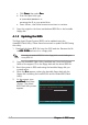
c. Click S t a r tt, then select R u n n. d. From the Open field, type D:\bootdisk\makeboot a: assuming that D: is your optical drive. e. Press , then follow screen instructions to continue. 2. Copy the original or the latest motherboard BIOS file to the bootable floppy disk. 4.1.2 Updating the BIOS The Basic Input/Output System (BIOS) can be updated using the AwardBIOS Flash Utility. Follow these instructions to update the BIOS using this utility. 1.
6. Type the BIOS file name in the F i l e N a m e t o P r o g r a m field, then press . AwardBIOS Flash Utility for ASUS V1.01 (C) Phoenix Technologies Ltd. All Rights Reserved For K8T890-8237-A8V-E-00 DATE: 09/10/2004 Flash Type - PMC Pm49FL004T LPC/FWH File Name to Program: A8V-E.BIN Message: Do You Want To Save Bios (Y/N) 7. Press when the utility prompts you to save the current BIOS file. The following screen appears. 8.
4.1.3 Saving the current BIOS file You can use the AwardBIOS Flash Utility to save the current BIOS file. You can load the current BIOS file when the BIOS file gets corrupted during the flashing process. To save the current BIOS file using the AwardBIOS Flash Utility: 1. Follow steps 1 to 6 of the previous section. 2. Press when the utility prompts you to save the current BIOS file. The following screen appears. AwardBIOS Flash Utility for ASUS V1.01 (C) Phoenix Technologies Ltd.
4.1.4 ASUS CrashFree BIOS 2 utility The ASUS CrashFree BIOS 2 is an auto recovery tool that allows you to restore the BIOS file when it fails or gets corrupted during the updating process. You can update a corrupted BIOS file using the motherboard support CD or the floppy disk that contains the updated BIOS file. Prepare the motherboard support CD or the floppy disk containing the updated motherboard BIOS before using this utility.
Recovering the BIOS from a floppy disk To recover the BIOS from the support CD: 1. Remove any CD from the optical drive, then turn on the system. 2. Insert the floppy disk with the original or updated BIOS file to the floppy disk drive. 3. The utility displays the following message and automatically checks the floppy disk for the original or updated BIOS file. Award BootBlock BIOS v1.0 Copyright (c) 2000, Award Software, Inc. BIOS ROM checksum error Detecting IDE ATAPI device...
4.1.5 ASUS EZ Flash utility The ASUS EZ Flash feature allows you to update the BIOS without having to go through the long process of booting from a floppy disk and using a DOS-based utility. The EZ Flash utility is built-in the BIOS chip so it is accessible by pressing + during the Power-On Self Tests (POST). To update the BIOS using EZ Flash: 1. Visit the ASUS website (www.asus.com) to download the latest BIOS file for the motherboard. 2.
4.1.6 ASUS Update utility The ASUS Update is a utility that allows you to manage, save, and update the motherboard BIOS in Windows® environment. The ASUS Update utility allows you to: • Save the current BIOS file • Download the latest BIOS file from the Internet • Update the BIOS from an updated BIOS file • Update the BIOS directly from the Internet, and • View the BIOS version information. This utility is available in the support CD that comes with the motherboard package.
Updating the BIOS through the Internet To update the BIOS through the Internet: 1. Launch the ASUS Update utility from the Windows® desktop by clicking Start > Programs > ASUS > ASUSUpdate > ASUSUpdate e. The ASUS Update main window appears. 2. Select U p d a t e B I O S f r o m t h e I n t e r n e t option from the drop-down menu, then click N e x tt. ASUS A8V-E Deluxe 3. Select the ASUS FTP site nearest you to avoid network traffic, or click A u t o S e l e c tt. Click N e x tt.
4. From the FTP site, select the BIOS version that you wish to download. Click Next. 5. Follow the screen instructions to complete the update process. The ASUS Update utility is capable of updating itself through the Internet. Always update the utility to avail all its features. Updating the BIOS through a BIOS file To update the BIOS through a BIOS file: 1. 2.
4.2 BIOS setup program This motherboard supports a programmable Low-Pin Count (LPC) chip that you can update using the provided utility described in section “4.1 Managing and updating your BIOS.” Use the BIOS Setup program when you are installing a motherboard, reconfiguring your system, or prompted to “Run Setup”. This section explains how to configure your system using this utility. Even if you are not prompted to use the Setup program, you can change the configuration of your computer in the future.
4.2.1 BIOS menu screen Menu items Menu bar Main Advanced Phoenix-Award BIOS CMOS Setup Utility Power Boot Exit System Time System Date Language 15 : 30 : 36 Wed, Sep 15 2004 [English] Legacy Diskette A: [1.44M, 3.5 in.
4.2.3 Legend bar At the bottom of the Setup screen is a legend bar. The keys in the legend bar allow you to navigate through the various setup menus. The following table lists the keys found in the legend bar with their corresponding functions.
4.2.7 Pop-up window Select a menu item then press to display a pop-up window with the configuration options for that item. Main Advanced Phoenix-Award BIOS CMOS Setup Utility Power Boot Exit System Time System Date 15 : 30 : 36 Wed, Sep 15 2004 Legacy Diskette A: [1.44M, 3.5 in.] Select Menu Item Specific Help A: Primary IDE Master Legacy Diskette [ST321122A] Primary IDE Slave [ASUS CDS520/A] Secondary IDE Master Disabled [None] ..... [ ] Secondary IDE Slave 360K , 5.25 in. [None] .....
4.3 Main menu When you enter the BIOS Setup program, the Main menu screen appears, giving you an overview of the basic system information. Refer to section “4.2.1 BIOS menu screen” for information on the menu screen items and how to navigate through them. Main Advanced Phoenix-Award BIOS CMOS Setup Utility Power Boot Exit System Time System Date Language 15 : 30 : 36 Wed, Sep 15 2004 [English] Legacy Diskette A: [1.44M, 3.5 in.
4.3.5 Primary and Secondary IDE Master/Slave While entering Setup, the BIOS automatically detects the presence of IDE devices. There is a separate sub-menu for each IDE device. Select a device item then press to display the IDE device information.
Capacity Displays the auto-detected hard disk capacity. This item is not configurable. Cylinder Shows the number of the hard disk cylinders. This item is not configurable. Head Shows the number of the hard disk read/write heads. This item is not configurable. Sector Shows the number of sectors per track. This item is not configurable. PIO Mode Sets the PIO mode for the IDE device. Configuration options: [Auto] [Mode 0] [Mode 1] [Mode 2] [Mode 3] [Mode 4] UDMA Mode Disables or sets the UDMA mode.
4.4 Advanced menu The Advanced menu items allow you to change the settings for the CPU and other system devices. Take caution when changing the settings of the Advanced menu items. Incorrect field values can cause the system to malfunction.
4.4.2 Chipset Phoenix-Award BIOS CMOS Setup Utility Advanced Chipset Select Menu DRAM Configuration Upstream LDT Bus Width Downstream LDT Bus Width LDT Bus Frequency VLink Mode Selection PEG Data Scrambling PE0-PE3 Data Scrambling Init Display First Chipset Vcore Adjustment F1:Help ESC: Exit ↑↓ : Select Item →←: Select Menu Item Specific Help [16 bit] [16 bit] [Auto] [By Auto] [Auto] [Enable] [PCI Slot [+1.
CAS# latency (Tcl) [Auto] Controls the latency between the SDRAM read command and the time the data actually becomes available. Configuration options: [Auto] [2.0] [2.5] [3.0] RAS# to CAS# delay (Trcd) [Auto] Controls the latency between the DDR SDRAM active command and the read/write command. Configuration options: [Auto] [2] [3] [4] [5] [6] [7] Min RAS# active time (Tras) [Auto] Sets the minimum RAS# active time.
PE0-PE3 Data Scrambling [Enable] Disables or enables the PCI Express™ 0 to PCI Express™ 3 data scrambling. Configuration options: [Disable] [Enable] Init Display First [PCI Slot] Allows you to select the graphics controller to use as the primary boot device. Configuration options: [PCI Slot] [PCIEx] Chipset Vcore Adjustment [+1.5 V] Sets the chipset vcore adjustment voltage. Configuration options: [+1.5 V] [+1.6 V] 4.4.
When the item Resources Controlled By is set to [Auto], the item IRQ Resources is grayed out and not user-configurable. Refer to the section “IRQ Resources” for information on how to enable this item. IRQ Resources This sub-menu is activated only when the R e s o u r c e s C o n t r o l l e d B y item is set to Manual.
4.4.
Onboard AC97 Audio [Auto] Allows you to disable or set the onboard AC97 audio controller. Configuration options: [Disabled] [Auto] Serial Port1 Address [3F8/IRQ4] Allows you to select the Serial Port1 base address. Configuration options: [Disabled] [3F8/IRQ4] [2F8/IRQ3] [3E8/IRQ4] [2E8/IRQ3] [Auto] Parallel Port Address [378/IRQ7] Allows you to select the Parallel Port base addresses.
4.4.5 USB Configuration The items in this menu allows you to change the USB-related features. Select an item then press to display the configuration options.
4.4.6 JumperFree Configuration Phoenix-Award BIOS CMOS Setup Utility Advanced JumperFree Configuration x x x x x x x Overclock Profile Overclock Options N.O.S. Option Frequency Configuration CPU Multiplier Hammer Vid control Memory Voltage Adjustment CPU Vcore Adjustment F1:Help ESC: Exit [Auto] Overclock 3% Overclock 3% Select Menu Item Specific Help Auto Startup 2.
The following items are user-configurable only when the AI Overclocking item is set to [Manual]. Phoenix-Award BIOS CMOS Setup Utility Advanced JumperFree Configuration Overclock Profile x Overclock Options x N.O.S. Option Frequency Configuration CPU Multiplier Hammer Vid control Memory Voltage Adjustment CPU Vcore Adjustment F1:Help ESC: Exit ↑↓ : Select Item →←: Select Menu [Auto] Disabled Disabled Select Menu Item Specific Help [Auto] [Startup] [2.
PCIEx clock Sync. to CPU [Enable] Enables or disables the PCI Express™ synchronous clock to the CPU. Configuration options: [Disabled] [Enabled] PCIEx Clock [XXX] (value is auto-detected) Allows you to set the PCI Express clock frequency. This item is user-configurable only when the P C I E x c l o c k S y n c . t o C P U item is set to Disabled. The BIOS detects the default value of this item. Press then key-in desired PCI Express clock frequency within range. PCI clock Sync.
Hammer Vid control [Startup] Sets the Hammer Voltage ID control. Configuration options: [Startup] [1.5625v] [1.550 v] [1.5375v] [1.525 v] [1.5125v] [1.500 v] [1.4875v] [1.475 v] [1.4625v] [1.450 v] [1.4375v] [1.425 v] [1.4125v] [1.400 v] [1.3875v] [1.375 v] [1.3625v] [1.350 v] [1.3375v] [1.325 v] [1.3125v] [1.300 v] [1.2875v] [1.275 v] [1.2625v] [1.250 v] [1.2375v] [1.225 v] [1.2125v] [1.200 v] [1.1875v] [1.175 v] [1.1625v] [1.150 v] [1.1375v] [1.125 v] [1.1125v] [1.100 v] [1.0875v] [1.075 v] [1.0625v] [1.
4.4.7 LAN Cable Status The items in this menu displays the status of the Local Area Network (LAN) cable.
4.4.9 Speech Configuration Phoenix-Award BIOS CMOS Setup Utility Advanced JumperFree Configuration Speech IC Reporter Report IDE Error Report System Booting F1:Help ESC: Exit ↑↓ : Select Item →←: Select Menu [Enabled] [Disabled] [Disabled] Select Menu Item Specific Help Enable/Disable Speech IC Controller -/+: Change Value Enter: Select Sub-menu F5: Setup Defaults F10: Save and Exit Speech IC Reporter [Enabled] Allows you to enable or disable the ASUS Speech POST Reporter™ feature.
4.4.10 Instant Music Phoenix-Award BIOS CMOS Setup Utility Advanced JumperFree Configuration Instant Music x Instant Music CD-ROM Drive [Disabled] Primary Master Select Menu Item Specific Help If enabled, power up by PS/2 keyboard function will be disabled. F1:Help ESC: Exit ↑↓ : Select Item →←: Select Menu -/+: Change Value Enter: Select Sub-menu F5: Setup Defaults F10: Save and Exit Instant Music [Disabled] Allows you to enable or disable the ASUS Instant Music feature.
4.5 Power menu The Power menu items allow you to change the settings for the Advanced Configuration and Power Interface (ACPI) and the Advanced Power Management (APM). Select an item then press to display the configuration options. Main Advanced Phoenix-Award BIOS CMOS Setup Utility Power Boot Exit ACPI Suspend Type ACPI APIC support APM Configuration Hardware Monitor F1:Help ESC: Exit 4.5.
4.5.
Power On By RTC Alarm [Disabled] Allows you to enable or disable RTC to generate a wake event. When this item is set to Enabled, the items Date (of Month) and Resume Time (hh:mm:ss) become configurable with set values. Configuration options: [Disabled] [Enabled] Date (of Month) [0] To set the date of alarm, highlight this item and press to display the Day of Month Alarm pop-up menu. Key-in a value within the specified range then press .
4.5.4 Hardware Monitor The items in this sub-menu displays the hardware monitor values automatically detected by the BIOS. It also allows you to change CPU Q-Fan feature-related parameters. Select an item then press to display the configuration options. Phoenix-Award BIOS CMOS Setup Utility Power Hardware Monitor x x x x M/B Temperature Current CPU1 Temperature Chassis Fan speed CPU Fan speed Chipset Fan speed Chassis Fan2 speed VCORE Voltage +12V Voltage +3.
CPU Target Temperature [xxxºC/xxxºF] Allows you to set the CPU Q-Fan temperature threshold when the CPU fan speed is increased to lower the CPU temperature. Configuration options: [10ºC/50ºF] [15ºC/59ºF] [20ºC/68ºF] [25ºC/77ºF] [30ºC/86ºF] [35ºC/95ºF] [40ºC/104ºF] [45ºC/113ºF] [50ºC/122ºF] [55ºC/131ºF] [60ºC/140ºF] [65ºC/149ºF] [70ºC/158ºF] [75ºC/167ºF] [80ºC/176ºF] [85ºC/185ºF] Temperature Tolerance [3ºC] Allows you to set the CPU temperature tolerance value.
4.6.
4.6.3 Hard Disk Drives Phoenix-Award BIOS CMOS Setup Utility Boot Hard Disk Drives 1. 1st Master: XXXXXXXXX 2. Bootable Add-in Cards Select Menu Item Specific Help Use <↑> or <↓> to select a device, then press <+> to move it up, or <-> to move it down the list. Press to exit this menu. F1:Help ESC: Exit ↑↓ : Select Item →←: Select Menu -/+: Change Value Enter: Select Sub-menu F5: Setup Defaults F10: Save and Exit 1.
4.6.
Typematic Rate (Chars/Sec) [6] Allows you to select the rate at which a character repeats when you hold a key. Configuration options: [6] [8] [10] [12] [15] [20] [24] [30] Typematic Delay (Msec) [250] Allows you to set the delay before keystrokes begin to repeat. Configuration options: [250] [500] [750] [1000] OS Select for DRAM > 64MB [Non-OS2] Set this item to OS2 only when you are running on an OS/2 operating system with an installed RAM of greater than 64 KB.
4.6.6 Security Phoenix-Award BIOS CMOS Setup Utility Boot Boot Settings Configuration Supervisor Password User Password Password Check F1:Help ESC: Exit ↑↓ : Select Item →←: Select Menu Clear Clear [Setup] -/+: Change Value Enter: Select Sub-menu Select Menu Item Specific Help Supervisor password controls full access, to change password. F5: Setup Defaults F10: Save and Exit Supervisor Password User Password These fields allow you to set passwords: To set a password: 1.
A note about passwords The Supervisor password is required to enter the BIOS Setup program preventing unauthorized access. The User password is required to boot the system preventing unauthorized use. Forgot your password? If you forget your password, you can clear it by erasing the CMOS Real Time Clock (RTC) RAM. The RAM data containing the password information is powered by the onboard button cell battery. If you need to erase the CMOS RAM, refer to section “2.6 Jumpers” for instructions.
4.7 Exit menu The Exit menu items allow you to load the optimal or failsafe default values for the BIOS items, and save or discard your changes to the BIOS items. Main Advanced Phoenix-Award BIOS CMOS Setup Utility Power Boot Exit Select Menu Exit & Save Changes Exit & Discard Changes Load Setup Default Discard Changes F1:Help ESC: Exit ↑↓ : Select Item →←: Select Menu Item Specific Help This option save data to CMOS and exiting the setup menu.
Load Setup Defaults This option allows you to load the default values for each of the parameters on the Setup menus. When you select this option or if you press , a confirmation window appears. Select Y e s to load default values. Select E x i t & S a v e C h a n g e s or make other changes before saving the values to the non-volatile RAM. Discard Changes This option allows you to discard the selections you made and restore the previously saved values.
4-46 Chapter 4: BIOS setup
This chapter describes the contents of the support CD that comes with the motherboard package.
Chapter summary 5.1 Installing an operating system ............................................. 5-1 5.2 Support CD information ........................................................ 5-1 5.3 Software information ........................................................... 5-9 5.4 RAID configurations ............................................................ 5-18 5.5 Creating a RAID driver disk ................................................. 5-26 5.6 Cool ‘n’ Quiet!™ Technology .............
5.1 Installing an operating system This motherboard supports Windows® 2000/2003 Server/XP operating systems (OS). Always install the latest OS version and corresponding updates to maximize the features of your hardware. 5.2 • Motherboard settings and hardware options vary. Use the setup procedures presented in this chapter for reference only. Refer to your OS documentation for detailed information.
5.2.2 Drivers menu The drivers menu shows the available device drivers if the system detects installed devices. Install the necessary drivers to activate the devices. VIA 4 in 1 drivers This item installs the following drivers: - VIA Registry (INF) driver - VIA ATAPI vendor support driver - VIA PCI IRQ Miniport driver. VIA IDE RAID Controller driver Installs the VIA 6420 RAID controller driver and application.
ASUS Wireless LAN adapter Drivers and Utility Installs the driver, utilities, and setup wizard for the ASUS WiFi-g™ wireless solution. Refer to the WiFi-g™ documentation for details. USB 2.0 Driver Installs the USB 2.0 driver. AMD Cool ‘n’ Quiet Driver Launches the AMD Cool ‘n’ Quiet!™ Technology driver installation wizard.
5.2.3 Utilities menu The Utilities menu shows the applications and other software that the motherboard supports. Marvell Yukon VCT Application Installs the Marvell® Yukon Virtual Cable Tester (VCT) application. The VCT is a cable diagnostic application that analyzes and reports LAN cable faults and shorts. See page 5-11 for details. AI Booster The ASUS AI Booster application allows you to overclock the CPU speed in a Windows® environment.
Microsoft DirectX Installs the Microsoft® DirectX 9.0 driver. The Microsoft DirectX® 9.0 is a multimedia technology that enhances computer graphics and sound. DirectX® improves the multimedia features of you computer so you can enjoy watching TV and movies, capturing videos, or playing games in your computer. Visit the Microsoft website (www.microsoft.com) for updates. Winbond Voice Editor This program is for recording and customizing wave files for the ASUS POST Reporter™.
5.2.4 ASUS Contact information Click the C o n t a c t tab to display the ASUS contact information. You can also find this information on the inside front cover of this user guide. 5.2.5 Other information The icons on the top right corner of the screen give additional information on the motherboard and the contents of the support CD. Click an icon to display the specified information. Motherboard Info Displays the general specifications of the motherboard.
Browse this CD Displays the support CD contents in graphical format. Technical support Form Displays the ASUS Technical Support Request Form that you have to fill out when requesting technical support.
Filelist Displays the contents of the support CD and a brief description of each in text format.
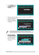
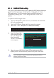
5.3 Software information Most of the applications in the support CD have wizards that will conveniently guide you through the installation. View the online help or readme file that came with the software application for more information. 5.3.1 ASUS MyLogo2™ The ASUS MyLogo2™ utility lets you customize the boot logo. The boot logo is the image that appears on screen during the Power-On Self-Tests (POST).
7. When the logo images appear on the right window pane, select an image to enlarge by clicking on it. 8. Adjust the boot image to your desired size by selecting a value on the R a t i o box. 9. When the screen returns to the ASUS Update utility, flash the original BIOS to load the new boot logo. 10. After flashing the BIOS, restart the computer to display the new boot logo during POST.
5.3.2 AI NET 2 The Marvell® Virtual Cable Tester™ (VCT) is a cable diagnostic utility that reports LAN cable faults and shorts using the Time Domain Reflectometry (TDR) technology. The VCT detects and reports open and shorted cables, impedance mismatches, pair swaps, pair polarity problems, and pair skew problems of up to 100 meters at one meter accuracy. The VCT feature reduces networking and support costs through a highly manageable and controlled network system.
5.3.3 Audio configurations The Realtek® ALC850 AC ‘97 audio CODEC provides 8-channel audio capability to deliver the ultimate audio experience on your PC. The software provides Jack-Sensing function (Line-In, Line-Out, Mic-In), S/PDIF out support and interrupt capability. The ALC850 also includes the Realtek® proprietary UAJ® (Universal Audio Jack) technology for three ports (Line-In, Line-Out and Mic-In), eliminating cable connection errors and giving users plug and play convenience.
To set the sound effect options: 1. From the Realtek Audio Control Panel, click the S o u n d E f f e c t button. 2. Click the shortcut buttons to change the acoustic environment, adjust the equalizer, or set the karaoke to your desired settings. 3. The audio settings take effect immediately after you click on the buttons. Click the Exit (X X ) button on the upper-right hand corner of the window to exit. 4.
Speaker Configuration This option allows you to set your speaker configuration. To set the speaker configuration: 1. From the Realtek Audio Control Panel, click the S p e a k e r C o n f i g u r a t i o n button. 2. Select from the combo list box your current speaker setup, then click A u t o T e s t to test your settings. Click the U A J A u t o m a t i c button to enable or disable the Universal Audio Jack(UAJ®) technology feature.
AI Audio feature The AI Audio feature works through the connector sensing option that allows you to check if your audio devices are connected properly. To start the connector sensing: 1. From the Realtek Audio Control Panel, click the C o n n e c t o r S e n s i n g button. 2. Click the B r a c k e t button to display connected audio devices. Click the O p t i o n button to change sensing options. 3. 4. Click the S t a r t button to start connection sensing.
6. 7. 8. If there are detected problems, make sure that your audio cables are connected to the proper audio jack and repeat connector sensing. Click the X button to exit EZ-connection dialog box. X ) button on the upper-right hand corner of the window Click the Exit (X to exit audio control panel. HRTF Demo This option shows a demo of the Head-Related Transfer Functions (HRTF). To start the HRTF demo: 1. 2. 3. 4. 5-16 From the Realtek Audio Control Panel, click the H R T F D e m o button.
General settings This option shows the audio settings and allows you to change the language setting or toggle the SoundEffect icon display on the Windows taskbar. To display the general settings: 1. From the Realtek Audio Control Panel, click the G e n e r a l button. 2. Click the option button to enable or disable the icon display on the Windows taskbar. Click the L a n g u a g e combo list box to change language display. 3. 4.
5.4 RAID configurations The motherboard comes with the VIA VT8237R Southbridge RAID controller that allows you to configure Serial ATA hard disk drives as RAID sets. The motherboard supports the following RAID configurations. R A I D 0 (Data striping) optimizes two identical hard disk drives to read and write data in parallel, interleaved stacks.
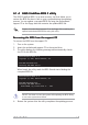
5.4.2 VIA RAID configurations The motherboard includes a high performance IDE RAID controller integrated in the VIA VT8237R southbridge chipset. It supports RAID 0 and RAID 1 with two independent Serial ATA channels. Entering VIA Tech RAID BIOS Utility 1. Boot-up your computer. 2. During POST, press to enter VIA RAID configuration utility. The following menu options will appear. The RAID BIOS information on the setup screen shown below is for reference only.
Create Array 1. From the VIA RAID BIOS utility main menu, select C r e a t e A r r a y then press < E n t e r > >. The main menu items on the upper-left corner of the screen are replaced with create array menu options. VIA Tech. RAID BIOS Ver 1.
4. 5. 6. Press to confirm or to return to the configuration options. If you selected , proceed to step 9. Select S e l e c t D i s k D r i v e ss, then press . Use arrow keys to select disk drive, then press to mark selected drive. An asterisk appears before a selected drive. Select B l o c k S i z e e, then press to set array block size. A list of valid array block sizes are displayed on a pop-up menu.
3. 4. From this point, you can auto-configure the RAID array by selecting A u t o S e t u p f o r D a t a S e c u r i t y or manually configure the RAID array for mirrored sets. If you want to auto-configure, proceed to the next step, otherwise, skip to step 6. Select A u t o S e t u p f o r D a t a S e c u r i t y and press . The following confirmation message appears. Auto create array will destroy all data on disks, Continue? (Y/N) 5. 6. 7.
RAID Span for capacity 1. From the create array menu, select A r r a y M o d e e, then press . The supported RAID configurations appear on a pop-up menu. RAID RAID RAID RAID 2. 3. 4. 0 for performance 1 for data protection 0/1 SPAN for capacity Select R A I D S P A N f o r c a p a c i t y then press . From this point, you can auto-configure the RAID array by selecting A u t o S e t u p f o r C a p a c i t y or manually configure the RAID array for spanned sets.
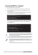
10. Press to confirm or to return to the configuration options. 11. Press to go back to main menu. Delete Array 1. From the VIA RAID BIOS utility main menu, select D e l e t e A r r a y then press . VIA Tech. RAID BIOS Ver 1.xx Create Array Delete Array Create/Delete Spare Select Boot Array Serial Number View Channel 2.
Serial Number View 1. 2. From the VIA RAID BIOS utility main menu, select S e r i a l N u m b e r V i e w then press . From the list of channel used for IDE RAID arrays, use the arrow keys to move the selection bar on each item. The serial number for the selected drive is displayed at the bottom of the screen. This option is useful for identifying same model disks. VIA Tech. RAID BIOS Ver 1.
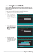
5.5 Creating a RAID driver disk A floppy disk with the RAID driver is required when installing Windows® 2000/XP operating system on a hard disk drive that is included in a RAID set. To create a RAID driver disk: 1. 2. Place the motherboard support CD into the CD-ROM drive. When the D r i v e r s menu appears, click M a k e V I A 6 4 2 0 R A I D D r i v e r D i s k to create a VIA RAID driver disk Or Browse the contents of the support CD to locate the driver disk utility and go to \ D r i v e r s \ V I A
5.6 Cool ‘n’ Quiet!™ Technology The motherboard supports the AMD Cool ‘n’ Quiet!™ Technology that dynamically and automatically change the CPU speed, voltage, and amount of power depending on the task the CPU performs. 5.6.1 Enabling Cool ‘n’ Quiet!™ Technology To enable Cool ‘n’ Quiet!™ Technology: 1. 2. 3. Turn on the system and enter BIOS by pressing the key during the Power On Self-Tests (POST).
5.6.2 Launching the Cool ‘n’ Quiet!™ software The motherboard support CD includes the Cool ‘n’ Quiet!™ software that enables you to view your system’s real-time CPU Frequency and voltage. Make sure to install the Cool ‘n’ Quiet!™ software from the motherboard support CD. Refer to section “5.2.3 Utilities menu”, for details. To launch the Cool ‘n’ Quiet!™ program: 1. 2. 3. 5-28 If you are using Windows® 2000, click the S t a r t button. Select Programs > ASUS > Cool & Quiet > Cool & Quiet.