Copyright Copyright ©2021 Fibonacci Wireless Inc. All rights reserved. Without the prior written permission of the copyright holder, any company or individual is prohibited to excerpt, copy any part of or the entire document, or transmit the document in any form. Notice The document is subject to update from time to time owing to the product version upgrade or other reasons. Unless otherwise specified, the document only serves as the user guide.
ERO Contents 3.4.2 SIM INHERITANCE 32 3.4.2.1 N.C. SIM Card 3.4.2.2 N.O. SIM Card Slot 3.4.3 SIM 3.4.4 SIM Design... 3.4.5 USB 3.0 Interface Application uu 35 3.5 Status Indicator 3.5.1 LED#1 Signal. 3.6 Interrupt Control... . 3.6.1 DISABLEMENT 37 3.7 ANT Unable Interface 3.8 Configuration Interface... 4 RATIO Frequency sissies sass A RF INTERFACE 41 4.1.1 RF Interface Functionality... 4.1.2 RF Connector Characteristic .. . 4.1.3 RF CONNECT DIMENSIONS 42 4.1.4 RF CONNECTION ASSEMBLIES 43 4.
ERO Contents 6.5 M.2 Card DISASSEMBLY rise 61 6.5.1 Card INSERTIONS 61 6.5.2 Mid-mount Connection with Single-Sided Module... 6.5.1 Top-mount Connection with Single-Sided Module 6.6 Storage 6.6.1 SLOT AGE 63 6.7 Packaging 6.7.1 Tray Package. 6.7.2 Tray Size Copyright © Fibonacci Wireless inc.
ERO 1 Foreword 1 Foreword 1.1 Introduction The document describes the electrical characteristics, RF performance, dimensions and application environment, etc. of FM101-GL (hereinafter referred to as FM101). With the assistance of the document and other instructions, the developers can quickly understand the hardware functions of FM101 modules and develop products. 1.2 Reference Standard The design of the product complies with the following standards: « 3GPP TS 34.121-1 V8.11.
ERO 1 Foreword « 3GPP TS 27.005 V10.0.1: Use of Data Terminal Equipment Data Circuit terminating Equipment (DTE-DCE) interface for Short Message Service (SMS) and Cell Broadcast Service (CBS) « PCI Express M.2 Specification Revere 1.3 Related Documents TBD Copyright © Fibonacci Wireless inc.
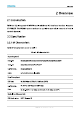
ERO 2 Overview Download 64 QAM MUST Modulation 3GPP Release 9 RF Characteristic HUE? B41 MIME 2x2 MIME Carrier Aggregation LTE DL 2CA 1) Don't support B39 in Japan 2) Don't support B40/42/43 in FCC/IC e 3) Don't support B48 in IC 4) CATS 11.5Mbps under developing 5) Don't support HUE in Japan 2.3 Key Features Table 2. Key features Specification CPU Qualcomm SDX12, 14nm process, ARM Cortex-A, up to 1.28 GHz Memory 2Gb LPDDR2+2Gb BAND Flash Supported OS Windows 10/Chrome /Linux Power Supply DC 3.135V to 4.
ERO Normal operating temperature: 10°C to +55°C 2 Overview Temperature Extended operating temperature: -30°C to +75°C" Storage temperature: —40°C to +85°C Interface: M.2 Key-B Physical Characteristics Dimension: Weight: TBD Interface Antenna WEAN Antenna x 2 Connector Support 2x2 MIME Dual SIM {one embedded Essie, USB 2.0 (For debug) USB 3.0 Function Disable# Interface Bodyguard LED Unable antenna 12C (Reserved) Software Protocol Stack IPV4/IPV6 AT Commands ~~ 3GPP TS 27.007 and 27.
Threescore 2 Overview Windows MAIM support Windows update AGNES 1) When temperature goes beyond normal operating temperature range of oO 10°C to +55°C, RF performance of module may be slightly off 3GPP specifications. 2.4 Application Block The peripheral applications for FM101 module are shown in Figure 1: Copyright © Fibonacci Wireless inc.
Threescore 2 Overview 2.5 Hardware Block Diagram The hardware block diagram in Figure 2 shows the main hardware functions of FM101 module, including base band and RF functions. Base band contains: + SUMTER TDD/LTE FDD controller + PMU * MCP (NANAK LPDDR2) * Application interface RF contains: * RF Transceiver RF DCDC/PA * RF Duplexes * Antenna Connector Copyright © Fibonacci Wireless inc.
Fess 3 Application Interface 3 Application Interface 3.1 M.2 Interface The FM101 module applies standard M.2 Key-B interface, with a total of 75 pins. 3.1.1 Pin Map CONFIGURE RFE_RFFE_SDATA RFE_RFFE_SCLK OD) 8v) FULL_GARD_POWER_OFFI(3 3/1 8) Figure 1. Pin map Copyright © Flamenco Wireless inc.
Finn e Pin “Notch” represents the gap of the gold fingers. 3.1.2 Pin Definition IO Parameter definition is as below table. Table 4.
Ein 3 Application Interface Table 5. Pin Definition Pin Pin Name I/O Reset Value Pin Description Type GND, FM101 M.2 module is 1 CONFIGURE O GND configured as the WEAN —SIC, USB 3.
Ein 3 Application Interface Pin Pin Name I/O Reset Value Pin Description Type 14 Notch Notch 15 Notch Notch 16 Notch Notch 17 Notch Notch 18 Notch Notch 19 Notch Notch 20 GPO PD GPIO(l), default low, reserved 18v NC, FM101 M.2 module is 21 CONFIGURE NC configured as the WEAN -SIC, USB 3.0 interface type 22 GPO | PD GPIO(l), default low, reserved 18v Wake up host, default low, 23 WOW WAN# Oo PD 18v Reserved 1.8V output for ANT Tuner, Power 24 ANT_TUNER_1V8 PO PD reserved. Supply /1.
Ein 3 Application Interface Pin Pin Name I/O Reset Value Pin Description Type 30 RESETTING o SIM reset signal 31 USB oc USB 3.0 transmit data plus 32 DULCIMER oO SIM clock signal Power 33 GND = GND Supply 34 UIM1_DATA I/O SIM data input/output 35 USB | USB 3.0 receive data minus 36 UIMI_PWR oOo SIM power supply, 37 USB | USB 3.0 receive data plus Power 39 GND GND Supply 12C clock, master mode, default 40 12C_SCL Oo PU 18v high, reserved 12C data, master mode, default 42 12C_SDA I/O PU 1.
Ein 3 Application Interface Pin Pin Name I/O Reset Value Pin Description Type Supply 73 GND GND GND 74 +33V PI Power input Power 75 CONFIGURE GC GND configured as the WEAN —SIC, Supply GND, FM101 M.2 module is USB 3.0 interface type Reset value is the status while module reset, not the status in working. Digital IO pins cannot be connected to power directly. The unused pins can be left floating. 3.2 Power Supply The power interface of FM101 module as shown in the following table: Table 6.
Forfeitures 3 Application Interface Table 7. Power rating Pin Pin Name I/O Pin Description Peak Current (mA) 2,4,70,72,74 +33V PI Power supply input 2500 1.8V power output for antenna 24 ANT TUNER V8 PO 200 tuner 36 UIM1_PWR PO SIM power supply 150 3.2.1 Power Supply The FM101 module should be powered through the +3.3V pins, and the power supply design is shown in Figure: — IW sis iy SING a Ee REA LEIDEN Loi Ada a Figure 4.
Ein 3 Application Interface Table 8. The filter capacitor design for power supply Recommended i} Application Description capacitance Reduce power fluctuations of the module in operation, requiring capacitors with low ESR. 220uF x 2 Voltage-stabilizing capacitors LDO or DC/DC power supply requires the capacitor with no less than 440uF in the power supply voltage range.
Forfeitures 3 Application Interface Burst transmit Burst transmit Drop VAT >3.135V Power supply : ooo perm Figure 5. Power supply requirement 3.2.2 Logic Level The FM101 module 1.8V logic level definition is shown in the following table: Table 9. Module 1.8V logic level definition Parameter Minimum Typical Maximum Unit Vou 171 18 1.89 v Vii? 13 18 1.89 Vv Vilma The FM101 module 3.3V logic level definition is shown in the following table: Table 10. Module 3.
Ein 3.2.3 Power Consumption 3 Application Interface In the condition of 3.3V power supply, the FM101 power consumption is shown in the following table: Parameter off Sepsis WCDMA-RMS LITE RMS Table 11. Power consumption Typical Mode Condition Current (mA) Power off Power supply, module power off TBD DROPBOX TBD MADMAN ~~ DROPBOX T8D DROPBOX TBD LTE FDD Paging cycle #128 frames (1.28s DRx cycle) TBD LTE TDD Paging cycle #128 frames (1.28s DRx cycle) TBD Radio Off flight mode TBD MADMAN Data call Band 1 @23.
Ein Parameter Mode LTE TDD Condition LTE FDD Data call Band 2 @DBMS LTE FDD Data call Band 3 @DBMS LTE FDD Data call Band 4 @DBMS LTE FDD Data call Band 5 @DBMS 3 Application Interface Typical Current (mA) TBD TBD TBD TBD LTE FDD Data call Band 7 @DBMS LTE FDD Data call Band 8 @DBMS LTE FDD Data call Band 12 @DBMS LTE FDD Data call Band 13 @DBMS LTE FDD Data call Band 14 @DBMS LTE FDD Data call Band 17 @DBMS TBD TBD TBD TBD TBD TBD LTE FDD Data call Band 18 @DBMS LTE FDD Data call Band 19 @DBMS LTE FDD Data
Forfeitures 3 Application Interface Typical Parameter Mode Condition Current (mA) LTE TDD Data call Band 39 @DBMS TBD LTE TDD Data call Band 40 @DBMS TBD LTE TDD Data call Band 41 @DBMS TBD LTE TDD Data call Band 41 @DBMS TBD LTE TDD Data call Band 42 @DBMS TBD LTE TDD Data call Band 43 @DBMS TBD LTE TDD Data call Band 48 @DBMS TBD The above data is the average value obtained by testing the sample for 6 high/medium/low channels in room temperature(ambient 25°C).
Forfeitures 3 Application Interface RESET# needs to be controlled by independent GPO, and not shared with other Oo devices on the host. RESET# is sensitive signal, so it should be kept away from RF interference and protected by ground. It should be neither near PCB edge nor route on surface layer to avoid being reset abnormally caused by ESD. 3.3.1 Module Start-Up 3.3.1.1 Start-up Circuit The CPO# (FULL_CARD_POWER_OFF #) pin needs an external 3.3V or 1.8V pull up for booting up.
Forfeitures 3 Application Interface +3.3v J tor CPO# RESET# typical TB's Mos se nei — Figure 7. Timing control for start-up Index Min. Recommended Max. Comment The delay time of power supply rising from OV up to for Oms 3.135 V stably. If power supply always ready, it can be ignored. ton 8ms 20ms The time from CPO# high to RESET# high. 3.3.
Forfeitures 3 Application Interface The module can be shut down by sending AT+CPWROFF command. When the module receives the software shutdown command, the module will start the finalization process (the reverse process of initialization), and it will be completed after tsd time (tsd is the waiting time from AP send AT+CPWROFF to AP receive OK, the max tsd is 5s). The control timing is shown in Figure 8: +3.3v CPO# RESET# ARTHROSCOPE fad Module State wm Finalization Figure 8.
Forfeitures 3 Application Interface 20ms, and module will restart after RESET# signal is released. When customer executes RESET# function, the PMU power will be turned off. The recommended circuit design is shown in the Figure 9: UT haw Baden BONED BERET aE Door Supine: Figure 9.
Forfeitures 3 Application Interface +3.3v CPO# RESET# tn PARATHION tu typical 20s Le west sme ER vii re Figure 11. Reset timing 2" Index Min. Recommended Max. Comment CPO# should be asserted after RESET#, toi 20ms 20ms refer section 3.3.2 Time to allow the WEAN module to fully discharge any residual voltages before the pin could be detox ~~ 500ms 500ms asserted again.
Ein supports SIM card. 3.4.1 SIM Pins 3 Application Interface The SIM pins description is shown in the following table: Pin Pin Name I/O Reset Value Description Type 36 UIMI_PWR PO SIM power supply 30 RESETTING oO SIM reset 32 UIMI_CLK oO SIM clock 34 INTIMIDATE Io SIM data, internal pull ~~ SIM card detect, internal 390 KQ pull-up. Active high, and high level 66 DETECTIVE | PD indicates SIM card is inserted; and 1.8v low level indicates SIM card is detached. 3.4.2 SIM Interface Circuit 3.4.2.1 N.C.
Forfeitures 3 Application Interface Figure 12. Reference circuit for N.C. SIM card slot The principles of the N.C.SIM card slot are described as follows: * When the SIM card is detached, it connects the short circuit between CD and SW pins, and drives the DETECTIVE pin low. * When the SIM card is inserted, it connects an open circuit between CD and SW pins, and drives the DETECTIVE pin high. 3.4.2.2 N.O. SIM Card Slot The reference circuit design for N.O.
Forfeitures 3 Application Interface card is inserted or detached by detecting the DETECTIVE pin state of the SIM card slot. The SIM card hot-plugging function can be configured by AT+MSMPD command, and the description for AT command is shown in the following table: Hot-plug AT Command Function Description Detection Default value, the SIM card hot-plug detection function is enabled. AT+MSMPD=1 Enable The module can detect whether the SIM card is inserted or not through the DETECTIVE pin state.
Forfeitures 3 Application Interface * The trace length between the SIM card slot and the module should not exceed 100mm, or it could reduce the signal quality. * The UIM_CLK and METADATA signal lines should be isolated by GND to avoid crosswalk interference. If it is difficult for the layout, the whole SIM signal lines should be wrapped with GND as a group at least.
Forfeitures 3 Application Interface 3.5 Status Indicator The FM101 module provides two signals to indicate the operating status of the module, and the status indicator pins is shown in the following table: Pin Pin Name I/O Reset Value Pin Description Level 10 LED# oD oT System status LED, drain output. 33v 23 WOW WAN# DO PD Wake up host, default low, Reserved 1.8V 3.5.
Forfeitures 3 Application Interface 0 The resistance of LED current-limiting resistor is selected according to the driving voltage and the driving current. 3.6 Interrupt Control The FM101 module provides two interrupt signals, and the pin definitions are as follows: Pin Pin Name I/O Reset Value Pin Description Type WEAN disable, default high, active 8 DISABLE# PU | ow Dynamic power reduction detect, 25 DPR PD default high, active low 3.6.
Forfeitures 3 Application Interface 3.6.2 DPR The FM101 module supports Bodyguard function by detecting the DPR pin. The voltage level of DPR is high by default, and when the SAR sensor detects the closing human body, the DPR signal will be pulled down. As the result, the module then lowers down its emission power to its default threshold value, thus reducing the RF radiation on the human body. The threshold of emission power can be set by the AT Commands.