Notebook PC Hardware User’s Manual ASU S WID E SCR EEN NOTEB OO K OFF ON E2896 / Oct 2006
Contents Table of Contents Table of Contents 1. Introducing the Notebook PC About This User’s Manual .......................................................................................... 6 Notes For This Manual........................................................................................... 6 Preparing your Notebook PC...................................................................................... 9 2. Knowing the Parts Top Side........................................................
Contents 4. Using the Notebook PC Operating System..................................................................................................... 36 Support Software ................................................................................................. 36 Automatic Touchpad Disabling (on selected models) ......................................... 36 Pointing Device.........................................................................................................
Contents 4
1.
1 Introducing the Notebook PC About This User’s Manual You are reading the Notebook PC User’s Manual. This User’s Manual provides information on the various components in the Notebook PC and how to use them. The following are major sections of this User’s Manuals: 1. Introducing the Notebook PC Introduces you to the Notebook PC and this User’s Manual. 2. Knowing the Parts Gives you information on the Notebook PC’s components. 3.
1 Introducing the Notebook PC Safety Precautions The following safety precautions will increase the life of the Notebook PC. Follow all precautions and LQVWUXFWLRQV ([FHSW DV GHVFULEHG LQ WKLV PDQXDO UHIHU DOO VHUYLFLQJ WR TXDOLÀHG SHUVRQQHO 'R QRW XVH GDPDJHG SRZHU FRUGV DFFHVVRULHV RU RWKHU SHULSKHUDOV 'R QRW XVH VWURQJ VROYHQWV VXFK DV WKLQQHUV benzene, or other chemicals on or near the surface. IMPORTANT! Disconnect the AC power and remove the battery pack(s) before cleaning.
1 Introducing the Notebook PC Transportation Precautions To prepare the Notebook PC for transport, you should turn it OFF and disconnect all external peripherals to prevent damage to the connectors. The hard disk drive’s head retracts when the power is turned OFF to prevent scratching of the hard disk surface during transport. Therefore, you should not transport the Notebook PC while the power is still ON.
1 Introducing the Notebook PC Preparing your Notebook PC These are only quick instructions for using your Notebook PC. Read the later pages for detailed information on using your Notebook PC. 2. Connect the AC Power Adapter 1. Install the battery pack 3 1 2 3. Open the Display Panel 4. Turn ON the Notebook PC 1.
1 10 Introducing the Notebook PC
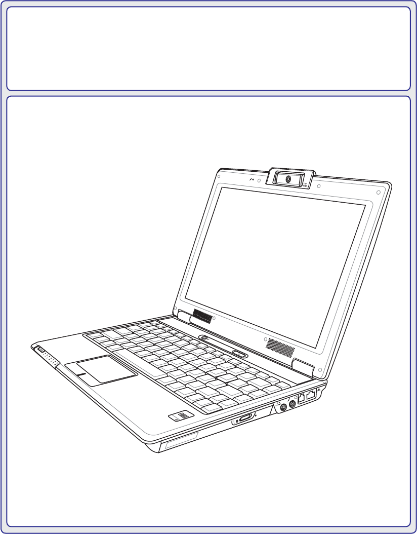
2. Knowing the Parts Basic sides of the Notebook PC NOTE: Photos and icons in this manual are used for artistic purposes only and do not show what is actually used in the product itself.
2 Knowing the Parts Top Side Refer to the diagram below to identify the components on this side of the Notebook PC. NOTE: The keyboard will be different for each territory. 1 2 3 4 5 6 7 10 8 9 6 Microphone (Built-in) 1 The built-in mono microphone can be used for video conferencing, voice narrations, or simple audio recordings.
Knowing the Parts 2 2 Camera Indicator The camera indicator shows when the built-in camera is in use. The camera may be auto-activated by supported software. 3 Camera (on selected models) The built-in camera allows picture taking or video recording. Can be used with video conferencing and other interactive applications. 4 Display Panel The display panel functions the same as a desktop monitor.
2 Knowing the Parts Bottom Side Refer to the diagram below to identify the components on this side of the Notebook PC. NOTE: The bottom side may vary in appearance depending on model. 1 2 3 7 4 5 6 WARNING! The bottom of the Notebook PC can get very hot. Be careful when handling the Notebook PC while it is in operation or recently been in operation. High temperatures are normal during charging or operation. Do not use on soft surfaces such as beds or sofas which may block the vents.
Knowing the Parts 1 2 Battery Pack The battery pack is automatically charged when the Notebook PC is connected to an AC power source and maintains power to the Notebook PC when AC power is not connected. This allows use when moving temporarily between locations. Battery time varies by usage DQG E\ WKH VSHFLÀFDWLRQV IRU WKLV 1RWHERRN 3& 7KH EDWWHU\ SDFN FDQQRW EH GLVDVVHPEOHG and must be purchased as a single unit.
2 Knowing the Parts Left Side Refer to the diagram below to identify the components on this side of the Notebook PC. 1 2 3 4 5 6 Display (Monitor) Output 1 7KH SLQ ' VXE PRQLWRU SRUW VXSSRUWV D VWDQGDUG 9*$ FRPSDWLEOH GHYLFH VXFK DV D PRQLWRU or projector to allow viewing on a larger external display. TV-Out Port 2 The TV-Out port is an S-Video connector that allows routing the Notebook PC’s display to a television or video projection device.
Knowing the Parts 6 2 Flash Memory Slot Normally a PCMCIA or USB memory card reader must be purchased separately in order to use memory cards from devices such as digital cameras, MP3 players, mobile SKRQHV DQG 3'$V 7KLV 1RWHERRN 3& KDV D EXLOW LQ PHPRU\ FDUG UHDGHU WKDW FDQ UHDG PDQ\ ÁDVK PHPRU\ FDUGV DV VSHFLÀHG ODWHU LQ WKLV PDQXDO 7KH EXLOW LQ PHPRU\ FDUG UHDGHU LV not only convenient, but also faster than most other forms of memory card readers because it utilizes the high-bandwidth PCI bus.
2 Knowing the Parts Right Side Refer to the diagram below to identify the components on this side of the Notebook PC. 1 2 3 4 5 6 7 8 Optical Drive 1 The Notebook PC comes in various models with different optical drives. The Notebook 3&·V RSWLFDO GULYH PD\ VXSSRUW FRPSDFW GLVFV &' DQG RU GLJLWDO YLGHR GLVFV '9' DQG PD\ KDYH UHFRUGDEOH 5 RU UH ZULWDEOH 5: FDSDELOLWLHV 6HH WKH PDUNHWLQJ VSHFLÀFDtions for details on each model.
Knowing the Parts 7 2 Modem Port The RJ-11 modem port with two pins is smaller than the RJ-45 LAN port and supports a standard telephone cable. The internal modem supports up to 56K V.90 transfers. The built-in connector allows convenient use without additional adapters. IMPORTANT! The built-in modem does not support the voltage used in digital phone systems. Do not connect the modem port to a digital phone system or else damage will occur to the Notebook PC.
2 Knowing the Parts Rear Side Refer to the diagram below to identify the components on this side of the Notebook PC. 1 1 2.0 2 3 USB Port (2.0/1.1) The USB (Universal Serial Bus) port is compatible with USB 2.0 or USB 1.1 devices such as keyboards, pointing devices, cameras, hard disk drives, printers, and scanners connected in a series up to 12Mbits/sec (USB 1.1) and 480Mbits/sec (USB 2.0).
Knowing the Parts 2 Front Side Refer to the diagram below to identify the components on this side of the Notebook PC. 1 1 Status Indicators (front) Status indicators represent various hardware/software conditions. See indicator details in section 3.
3 22 Getting Started
3.
3 Getting Started Power System Using AC Power The Notebook PC power is comprised of two parts, the power adapter and the battery power system. The power adapter converts AC power from a wall RXWOHW WR WKH '& SRZHU UHTXLUHG E\ WKH 1RWHERRN PC. Your Notebook PC comes with a universal $& '& DGDSWHU 7KDW PHDQV WKDW \RX PD\ FRQQHFW the power cord to any 100V-120V as well as 220V240V outlets without setting switches or using SRZHU FRQYHUWHUV 'LIIHUHQW FRXQWULHV PD\ UHTXLUH that an adapter be used to connec
Getting Started 3 Using Battery Power The Notebook PC is designed to work with a removable battery pack. The battery pack consists of a set of battery cells housed together. A fully charged pack will provide several hours of battery life, which can be further extended by using power management features through the BIOS setup. Additional battery packs are optional and can be purchased separately through a Notebook PC retailer.
3 Getting Started Powering ON the Notebook PC The Notebook PC’s power-ON message appears on the screen when you turn it ON. If necessary, you may adjust the brightness by using the hot keys. If you need to run the BIOS Setup to set or modify the V\VWHP FRQÀJXUDWLRQ SUHVV >) @ XSRQ ERRWXS WR HQWHU WKH %,26 6HWXS ,I \RX SUHVV >7DE@ GXULQJ WKH VSODVK VFUHHQ VWDQGDUG ERRW LQIRUPDWLRQ VXFK DV WKH %,26 YHUVLRQ FDQ EH VHHQ 3UHVV >(6&@ DQG \RX ZLOO be presented with a boot menu with selections to boot from
Getting Started 3 Checking Battery Power The battery system implements the Smart Battery standard under the Windows environment, which allows the battery to accurately report the amount of charge left in the battery. A fully-charged battery pack provides the Notebook PC a few hours of working power. But WKH DFWXDO ÀJXUH YDULHV GHSHQGLQJ RQ KRZ \RX XVH WKH SRZHU VDYLQJ features, your general work habits, the CPU, system memory size, and the size of the display panel.
3 Getting Started Restarting or Rebooting After making changes to your operating system, you may be prompted to restart the system. Some installation processes will provide a dialog box to allow restart. To restart the system manually, click :LQGRZV 6WDUW EXWWRQ DQG VHOHFW 6KXW 'RZQ DQG then choose Restart. (Screens are different depending on security settings.
3 Getting Started Special Keyboard Functions 1.3 MEGA PIXELS Colored Hot Keys 7KH IROORZLQJ GHÀQHV WKH FRORUHG KRW NH\V RQ WKH 1RWHERRN 3&·V NH\ERDUG 7KH FRORUHG FRPPDQGV FDQ RQO\ EH DFFHVVHG E\ ÀUVW SUHVVLQJ DQG KROGLQJ WKH IXQFWLRQ key while pressing a key with a colored command. ASUS WIDE SCREEN NOTEBOOK OFF ON NOTE: The Hot Key locations on the function keys may vary depending on model but the functions should remain the same. Follow the icons instead of the function keys.
3 Getting Started Colored Hot Keys (Cont.) Speaker Down Icon (F11): 'HFUHDVHV WKH VSHDNHU YROXPH RQO\ LQ :LQGRZV 26 Speaker Up Icon (F12): Increases the speaker volume (only in Windows OS) Num Lk (Ins): Toggles the numeric keypad (number lock) ON and OFF. Allows you to use a larger portion of the keyboard for number entering. Scr Lk (Del): Toggles the “Scroll Lock” ON and OFF. Allows you to use a larger portion of the keyboard for cell navigation.
Getting Started 3 Microsoft Windows Keys There are two special Windows keys on the keyboard as described below. The key with the Windows Logo activates the Start menu located at the bottom left of the Windows desktop. The other key, that looks like a Windows menu with a small cursor, activates the properties menu and is equivalent to pressing the right mouse button on a Windows object.
3 Getting Started Switches and Status Indicators Switches 1.3 MEGA PIXELS ASUS WIDE SCREEN NOTEBOOK OFF ON Power4 Gear+ Key The Power4 Gear+ button toggles power savings between various power saving modes. The power saving modes control many aspects of the Notebook PC to maximize performance versus battery time. When you are using an AC power adapter, Power4 Gear+ will switch between modes in the AC power mode segment.
Getting Started Status Indicators 3 1.3 MEGA PIXELS Front ASUS WIDE SCREEN NOTEBOOK OFF ON Wireless Indicator This is only applicable on models with built-in wireless LAN and/or built-in Bluetooth. When the built-in wireless LAN and/or built-in Bluetooth is enabled, this indicator will light. (Windows software settings are necessary.) Bluetooth Indicator This is only applicable on models with internal Bluetooth (BT).
4 34 Using the Notebook PC
4.
4 Using the Notebook PC Operating System This Notebook PC may offer (depending on territory) its customers the choice of a pre-installed operating system such as Microsoft Windows XP. The choices and languages will depend on the territory. The levels of hardware and software support may vary depending on the installed operating system. The stability and compatibility of other operating systems cannot be guaranteed.
Using the Notebook PC 4 Pointing Device The Notebook PC’s integrated touchpad pointing device is fully compatible with all two/three-button and scrolling knob PS/2 mice. The touchpad is pressure sensitive and contains no moving parts; therefore, mechanical failures can be avoided. A device driver is still required for working with some application software. Cursor Movement IMPORTANT! Do not use any objects in SODFH RI \RXU ÀQJHU WR RSHUDWH WKH WRXFKpad or else damage may occur to the touchpad’s surface.
4 Using the Notebook PC Touchpad Usage Illustrations Clicking/Tapping - :LWK WKH FXUVRU RYHU DQ LWHP SUHVV WKH OHIW EXWWRQ RU XVH \RXU ÀQJHUWLS WR WRXFK WKH WRXFKSDG OLJKWO\ NHHSLQJ \RXU ÀQJHU RQ WKH WRXFKSDG XQWLO WKH LWHP LV VHOHFWHG 7KH VHOHFWHG LWHP ZLOO change color. The following 2 examples produce the same results. Clicking Press the left cursor button and release. Tapping Lightly but rapidly strike the touchpad.
Using the Notebook PC 4 Dragging - 'UDJJLQJ PHDQV WR SLFN XS DQ LWHP DQG SODFH LW DQ\ZKHUH RQ WKH VFUHHQ \RX ZLVK
4 Using the Notebook PC Storage Devices 6WRUDJH GHYLFHV DOORZ WKH 1RWHERRN 3& WR UHDG RU ZULWH GRFXPHQWV SLFWXUHV DQG RWKHU ÀOHV WR YDULRXV data storage devices. This Notebook PC has the following storage devices: • • • • Expansion Card Optical drive Flash memory reader Hard disk drive Expansion Card One 26pin Express card slot is available to support one ExpressCard/34mm or one ExpressCard/54mm expansion card. This new interface is faster by using a serial bus supporting USB 2.
Using the Notebook PC 4 Optical Drive Inserting an optical disc 1. While the Notebook PC’s power is ON, press the drive’s eject button and the tray will eject out partially. 2. Gently pull on the drive’s front panel and slide the tray completely out. Be careful not to touch WKH &' GULYH OHQV DQG RWKHU PHFKDQLVPV 0DNH sure there are no obstructions that may get jammed under the drive’s tray. 3. Hold the disc by the edge and face the disc’s 4. Slowly push the drive’s tray back in.
4 Using the Notebook PC Optical Drive (Cont.) Removing an optical disc Emergency eject Actual location will vary by model. Eject the tray and gently pry the edge of the disc upwards at an angle to remove the disc from the hub. The emergency eject is located in a hole on the optical drive and is used to eject the optical drive tray LQ FDVH WKH HOHFWURQLF HMHFW GRHV QRW ZRUN 'R QRW use the emergency eject in place of the electronic eject.
Using the Notebook PC 4 Flash Memory Card Reader Normally a PCMCIA memory card reader must be purchased separately in order to use memory cards IURP GHYLFHV VXFK DV GLJLWDO FDPHUDV 03 SOD\HUV PRELOH SKRQHV DQG 3'$V 7KLV 1RWHERRN 3& KDV D VLQJOH EXLOW LQ PHPRU\ FDUG UHDGHU WKDW FDQ UHDG WKH IROORZLQJ ÁDVK PHPRU\ FDUGV 6HFXUH 'LJLWDO 6' 0XOWL 0HGLD &DUG 00& 0HPRU\ 6WLFN 06 0HPRU\ 6WLFN 6HOHFW 06 6HOHFW 0HPRU\ 6WLFN 'XR ZLWK 06 DGDSWHU 0HPRU\ 6WLFN 3UR DQG 0HPRU\ 6WLFN 3UR 'X
4 Using the Notebook PC Connections NOTE: The built-in modem and network cannot be installed later as an upgrade. After purchase, modem and/or network can be installed as an expansion card. Modem Connection The telephone wire used to connect the Notebook PC’s internal modem should have either two or four wires (only two wires (telephone line #1) is used by the modem) and should have an RJ-11 connector on both ends.
Using the Notebook PC 4 Network Connection Connect a network cable, with RJ-45 connectors on each end, to the modem/network port on the Notebook PC and the other end to a hub or switch. For 100 BASE-TX / 1000 BASE-T speeds, your network cable must be category 5 or better (not category 3) with twisted-pair wiring. If you plan on running the interface at 100/1000Mbps, it must be connected to a 100 BASE-TX / 1000 BASE-T hub (not a BASE-T4 KXE )RU %DVH 7 XVH FDWHJRU\ RU WZLVWHG SDLU ZLULQJ
4 Using the Notebook PC Wireless LAN Connection (on selected models) The optional built-in wireless LAN is a compact easy-to-use wireless Ethernet adapter. Implementing the IEEE 802.11 standard for wireless LAN (WLAN), the optional built-in wireless LAN is capable of IDVW GDWD WUDQVPLVVLRQ UDWHV XVLQJ 'LUHFW 6HTXHQFH 6SUHDG 6SHFWUXP '666 DQG 2UWKRJRQDO )UHTXHQF\ 'LYLVLRQ 0XOWLSOH[LQJ 2)'0 WHFKQRORJLHV RQ *+] *+] IUHTXHQFLHV 7KH RSWLRQDO EXLOW LQ ZLUHless LAN is backward compatible with the earli
Using the Notebook PC 4 Bluetooth Wireless Connection (on selected models) Notebook PCs with Bluetooth technology eliminates the need for cables for connecting BlueWRRWK HQDEOHG GHYLFHV ([DPSOHV RI %OXHWRRWK HQDEOHG GHYLFHV PD\ EH 1RWHERRN 3&V 'HVNWRS 3&V PRELOH SKRQHV DQG 3'$V d3 # m6 ɣɧ ɲɶ ɤɨ ɳɷ ? ɥɩ ɴɸ ɦɵ ɹ 8 t ɟɢ ɰɱ 0+ 5 j ɞɡɯ 2aɝɠɮ ɬɛ ɘɭ ɚɫ ɕ əɪ a/A ɜ * 7p ɗ 4gɖ 1 Bluetooth-enabled mobile phones
4 Using the Notebook PC Power Management Modes The Notebook PC has a number of automatic or adjustable power saving features that you can use to maximize battery life and lower Total Cost of Ownership (TCO). You can control some of these features through the Power menu in the BIOS Setup. ACPI power management settings are made through the operating system.
Using the Notebook PC 4 Power State Summary STATE ENTRY EVENT EXIT EVENT “Stand by” • “Stand by” through Windows Start button • Timer as set though “Power Management” in Windows Control Panel (higher priority) • Any device • Battery low STR (“Stand by”) (Suspend-to-RAM) • Hotkey (see “Colored Hotkeys” under “Special • Signal from modem port Keyboard Functions” in the previous section) • Power button or any key STD (“Hibernate”) (Suspend-to-Disk) • Hotkey (see “Colored Hotkeys” under “Special • Po
4 Using the Notebook PC Stand by and Hibernate Power management settings can be found in the Windows control panel. The following shows the power RSWLRQV SURSHUWLHV LQ :LQGRZV
Appendix Optional Accessories Optional Connections Glossary Declarations and Safety Statements Notebook PC Information 51
A Appendix Optional Accessories These items, if desired, come as optional items to complement your Notebook PC. USB Hub (Optional) Attaching an optional USB hub will increase your USB ports and allow you to quickly connect or disconnect many USB peripherals through a single cable. USB Keyboard and Mouse Attaching an external USB keyboard will allow data entry to be more comfortable. Attaching an external USB mouse will allow Windows navigation to be more comfortable.
Appendix A Optional Connections These items, if desired, may be purchased from third-parties. Printer Connection One or more USB printers can be simultaneously used on any USB port or USB hub.
A Appendix Glossary $&3, $GYDQFHG &RQÀJXUDWLRQ DQG 3RZHU 0DQDJHPHQW ,QWHUIDFH Modern standard for reducing power usage in computers. APM (Advanced Power Management) Modern standard for reducing power usage in computers. AWG (American Wire Gauge) NOTE: This table is for general reference only and should not be used as a source of the American Wire Gauge standard as this table may not be current or complete. Gauge AWG 33 32 30 29 27 26 25 Diam (mm) 0.18 0.19 0.20 0.25 0.30 0.35 0.40 0.45 Area (mm2) 0.
Appendix A Clock Throttling Chipset function which allows the processor’s clock to be stopped and started at a known duty cycle. Clock throttling is used for power savings, thermal management, and reducing processing speed. CPU (Central Processing Unit) The CPU, sometimes called “Processor,” actually functions as the “brain” of the computer. It interprets and executes program commands and processes data stored in memory.
A Appendix Kensington® Locks Kensington® locks (or compatible) allow the Notebook PC to be secured usually using a metal cable and ORFN WKDW SUHYHQW WKH 1RWHERRN 3& WR EH UHPRYHG IURP D À[HG REMHFW 6RPH VHFXULW\ SURGXFWV PD\ DOVR include a motion detector to sound an alarm when moved.
Appendix A RAM (Random Access Memory) RAM (usually just called memory) is the place in a computer where the operating system, application programs, and data in current use are temporarily kept so that they can be quickly reached by the computer’s processor instead of having to read from and write to slower storage such as the hard disk or optical disc.
A Appendix Declarations and Safety Statements DVD-ROM Drive Information 7KH 1RWHERRN 3& FRPHV ZLWK DQ RSWLRQDO '9' 520 GULYH RU D &' 520 GULYH ,Q RUGHU WR YLHZ '9' WLWOHV \RX PXVW LQVWDOO \RXU RZQ '9' YLHZHU VRIWZDUH 2SWLRQDO '9' YLHZHU VRIWZDUH PD\ EH SXUFKDVHG ZLWK WKLV 1RWHERRN 3& 7KH '9' 520 GULYH DOORZV WKH XVH RI ERWK &' DQG '9' GLVFV Regional Playback Information 3OD\EDFN RI '9' PRYLH WLWOHV LQYROYHV GHFRGLQJ 03(* YLGHR GLJLWDO $& DXGLR DQG GHFU\SWLRQ RI &66 protected content.
Appendix A Internal Modem Compliancy The Notebook PC with internal modem model complies with JATE (Japan), FCC (US, Canada, Korea, 7DLZDQ DQG &75 7KH LQWHUQDO PRGHP KDV EHHQ DSSURYHG LQ DFFRUGDQFH ZLWK &RXQFLO 'HFLVLRQ 98/482/EC for pan-European single terminal connection to the public switched telephone network (PSTN).
A Appendix Internal Modem Compliancy (Cont.) This table shows the countries currently under the CTR21 standard.
Appendix A Federal Communications Commission Statement This device complies with FCC Rules Part 15. Operation is subject to the following two conditions: • • This device may not cause harmful interference, and This device must accept any interference received, including interference that may cause undesired operation. This equipment has been tested and found to comply with the limits for a class B digital device, pursuant to Part 15 of the Federal Communications Commission (FCC) rules.
A Appendix FCC Radio Frequency Interference Requirements 7KLV GHYLFH LV UHVWULFWHG WR ,1'225 86( GXH WR LWV RSHUDWLRQ LQ WKH WR *+] IUHTXHQF\ UDQJH FCC requires this product to be used indoors for the frequency range 5.15 to 5.25GHz to reduce the potential for harmful interference to co-channel of the Mobile Satellite Systems. IMPORTANT: This device and its antenna(s) must not be co-located or operating in conjunction with any other antenna or transmitter.
Appendix A Wireless Operation Channel for Different Domains N. America Japan Europe ETSI 2.412-2.462 GHz 2.412-2.484 GHz 2.412-2.472 GHz Ch01 through CH11 Ch01 through Ch14 Ch01 through Ch13 France Restricted Wireless Frequency Bands Some areas of France have a restricted frequency band. The worst case maximum authorized power indoors are: • • 10mW for the entire 2.4 GHz band (2400 MHz–2483.5 MHz) 100mW for frequencies between 2446.5 MHz and 2483.
A Appendix UL Safety Notices Required for UL 1459 covering telecommunications (telephone) equipment intended to be electrically connected to a telecommunication network that has an operating voltage to ground that does not exceed 200V peak, 300V peak-to-peak, and 105V rms, and installed or used in accordance with the National Electrical Code (NFPA 70). When using the Notebook PC modem, basic safety precautions should always be followed to reduce the ULVN RI ÀUH HOHFWULF VKRFN DQG LQMXU\ WR SHUVRQV LQFO
Appendix A Nordic Lithium Cautions (for lithium-ion batteries) CAUTION! 'DQJHU RI H[SORVLRQ LI EDWWHU\ LV LQFRUUHFWO\ UHSODFHG 5HSODFH RQO\ ZLWK WKH VDPH RU HTXLYDOHQW W\SH UHFRPPHQGHG E\ WKH PDQXIDFWXUHU 'LVSRVH RI XVHG EDWWHULHV DFFRUGLQJ WR WKH PDQXIDFWXUHU·V instructions. (English) ATTENZIONE! Rischio di esplosione della batteria se sostituita in modo errato. Sostituire la batteria con un una di tipo uguale o equivalente consigliata dalla fabbrica. Non disperdere le batterie nell’ambiente.
A Appendix Optical Drive Safety Information Laser Safety Information ,QWHUQDO RU H[WHUQDO RSWLFDO GULYHV VROG ZLWK WKLV 1RWHERRN 3& FRQWDLQV D &/$66 /$6(5 352'8&7 /DVHU FODVVLÀFDWLRQV FDQ EH IRXQG LQ WKH JORVVDU\ DW WKH HQG RI WKLV XVHU·V PDQXDO :$51,1* 0DNLQJ DGMXVWPHQWV RU SHUIRUPLQJ SURFHGXUHV RWKHU WKDQ WKRVH VSHFLÀHG in the user’s manual may result in hazardous laser exposure. Do not attempt to disassemble the optical drive.
Appendix A CTR 21 Approval (for Notebook PC with built-in Modem) Danish Dutch English Finnish French German Greek Italian Portuguese Spanish Swedish 67
A Appendix Notebook PC Information This page is provided for recording information concerning your Notebook PC for future reference or IRU WHFKQLFDO VXSSRUW .
Copyright Information No part of this manual, including the products and software described in it, may be reproduced, transmitted, transcribed, stored in a retrieval system, or translated into any language in any form or by any means, except documentation kept by the purchaser for backup purposes, without the express written permission of ASUSTeK COMPUTER INC. (“ASUS”). $686 3529,'(6 7+,6 0$18$/ ´$6 ,6µ :,7+287 :$55$17< 2) $1< .