T3-P5G965 ASUS PC (Desktop Barebone)
E3290 June 2007 Copyright © 2007 ASUSTeK COMPUTER INC. All Rights Reserved. No part of this manual, including the products and software described in it, may be reproduced, transmitted, transcribed, stored in a retrieval system, or translated into any language in any form or by any means, except documentation kept by the purchaser for backup purposes, without the express written permission of ASUSTeK COMPUTER INC. (“ASUS”).
Table of contents Notices................................................................................................. vi Safety information...............................................................................vii About this guide..................................................................................viii System package contents..................................................................... x Chapter 1: System introduction 1.1 Welcome!..........................................
Table of contents 3.3.2 Drivers menu............................................................ 3-3 3.3.3 Utilities menu........................................................... 3-4 3.3.4 ASUS contact information....................................... 3-6 3.3.5 Other information.................................................... 3-6 Chapter 4: Motherboard info 4.1 Introduction........................................................................... 4-2 4.2 Motherboard layout................
Table of contents 5.5 5.6 5.7 5.8 5.4.2 CPU Configuration.................................................. 5-19 5.4.3 Chipset................................................................... 5-20 5.4.4 Onboard Devices Configuration.............................. 5-22 5.4.5 PCI PnP................................................................... 5-23 Power menu......................................................................... 5-25 5.5.1 Suspend Mode ..................................
Notices Federal Communications Commission Statement This device complies with Part 15 of the FCC Rules. Operation is subject to the following two conditions: • This device may not cause harmful interference, and • This device must accept any interference received including interference that may cause undesired operation. This equipment has been tested and found to comply with the limits for a Class B digital device, pursuant to Part 15 of the FCC Rules.
Safety information Electrical safety • To prevent electrical shock hazard, disconnect the power cable from the electrical outlet before relocating the system. • When adding or removing devices to or from the system, ensure that the power cables for the devices are unplugged before the signal cables are connected. • If the power supply is broken, do not try to fix it by yourself. Contact a qualified service technician or your retailer.
About this guide Audience This guide provides general information and installation instructions about the ASUS T3-P5G965 barebone system. This guide is intended for experienced users and integrators with hardware knowledge of personal computers. How this guide is organized This guide contains the following parts: 1. Chapter 1: System introduction This chapter gives a general description of the ASUS T2-PH1.
Conventions used in this guide WARNING: Information to prevent injury to yourself when trying to complete a task. CAUTION: Information to prevent damage to the components when trying to complete a task. IMPORTANT: Instructions that you MUST follow to complete a task. NOTE: Tips and additional information to aid in completing a task. Where to find more information Refer to the following sources for additional information and for product and software updates. 1.
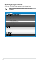
System package contents Check your T3-P5G965 system package for the following items. If any of the items is damaged or missing, contact your retailer immediately. Item description 1. ASUS T3-P5G965 barebone system with • ASUS motherboard • 250 W PFC power supply unit • Gigabit LAN port • CPU fan and heatsink assembly • 1 x 5.25” drive bays • 2 x 3.5” hard disk drive bay • 6 x USB 2.0 ports • 2 x IEEE 1394a ports • S/PDIF IN&OUT port • 7-in-1 storage card reader 2.
This chapter gives a general description of the ASUS T3-P5G965. The chapter lists the system features including introduction on the front and rear panel, and internal components.
1.1 Welcome! Thank you for choosing the ASUS T3-P5G965! The ASUS T3-P5G965 is an all-in-one barebone system with a versatile home entertainment feature. The system comes in a stylish mini-tower casing, and powered by the ASUS motherboard that supports the Intel® Pentium® 4 processor in the 775-land package with 533/800/1066 MHz FSB and up to 2 GB system memory. With audio functions, extensive connectivity, and Gigabit LAN capability, the T3-P5G965 is designed for the sophisticated.
1.3 Front panel (internal) The optical drive(s), storage card reader slots, and several I/O ports are located inside the front panel doors. Open the front panel door by pushing it downwards. 5 6 10 7 11 8 12 9 13 14 5. Optical Drive (optional). This is for the optical disks. 6. CompactFlash®/Microdrive™ card slot . This slot is for a CompactFlash®/Microdrive™ storage card. 7. Memory Stick®/Memory Stick Pro™ card slot. This slot is for a Memory Stick®/Memory Stick Pro™ storage card. 8.
1.4 Rear panel The system rear panel includes the power connector and several I/O ports that allow convenient connection of devices. 27 15 28 16 29 17 30 31 32 LINE IN FRONT MIC IN 19 CTR BASS SIDE SPK REAR SPK 18 20 33 34 eSATA 21 22 35 23 36 24 25 26 15. Expansion slot covers. Remove these covers when installing expansion cards. 16. Expansion slots. Use these slots when installing expansion cards. 17. Rear surround speakers.
26. 6-pin IEEE 1394a port . This port provides high-speed connectivity for IEEE 1394a-compliant audio/video devices, storage peripherals, and other PC devices. 27. Chassis vent. This vent is for the fan that provides ventilation inside the system chassis. 28. Expansion card lock. This lock secures installed expansion cards. See page 2-15 for details. 29. S/PDIF Out port. This port connects your audio system for 5.1channel surround sound and enhanced 3D audio. 30. Center & woofer speakers. 31. Line In port .
1.5 Internal components The illustration below is the internal view of the system when you remove the top cover and the power supply unit. The installed components are labeled for your reference. Proceed to Chapter 2 for instructions on installing additional system components. The illustration shows an open chassis lifted at a 90o angle. 2 1 3 6 5 4 8 7 1. ASUS motherboard 2. LGA775 socket with PnP cap 3. DIMM sockets 4. Serial ATA connectors 5.
Chapter 2 Basic installation This chapter provides step-by-step instructions on how to install components in the system.
2.1 Preparation Before you proceed, make sure that you have all the components you plan to install in the system. Basic components to install 1. Central Processing Unit (CPU) 2. DDR2 Dual Inline Memory Module (DIMM) 3. Expansion card(s) 4. Hard disk drive 5. Optical drive Tool Philips (cross) screw driver 2.2 Before you proceed Take note of the following precautions before you install components into the system.
2.3 Removing the cover To remove the cover: 1. On the rear panel, locate the three screws that secure the cover to 1 the chassis. FRONT LINE IN MIC IN SIDE SPK CTR BASS REAR SPK eSATA 1 2. 1 Use a Phillips screw driver to remove the cover screws. Keep the screws for later use. 2 2 2 3. Slightly pull the cover toward the rear panel until the side tabs are disengaged from the chassis. 4. Lift the cover, then set aside.
2.4 Removing the power supply unit You need to remove the power supply unit (PSU) before you can install a central processing unit (CPU) and other system components. To remove the PSU: 1. Lay the system chassis on its side on a flat and stable surface. 2. Disconnect the optical drive power connector. 3. Locate and remove the two screws that secures the PSU to the chassis. 4. Lift the PSU in the direction of the arrow to a 90º angle. When removing the PSU, make sure to hold or support it firmly.
2.5 CPU installation 2.5.1 • Your boxed Intel® Pentium® 4 LGA775 processor package should come with installation instructions for the CPU, heatsink, and the retention mechanism. If the instructions in this section do not match the CPU documentation, follow the latter. • Check your motherboard to make sure that the PnP cap is on the CPU socket and the socket contacts are not bent.
2. Press the load lever with your thumb (A), then move it to the left (B) until it is released from the retention tab. To prevent damage to the socket pins, do not remove the PnP cap unless you are installing a CPU. 3. 4. Retention tab A B Load lever Lift the load lever in the direction of the arrow to a 135º angle. PnP cap Load plate Lift the load plate with your thumb and forefinger to a 100º angle (4A), then push the PnP cap from the load plate window to remove (4B). 4B 4A 3 5.
6. Close the load plate (A), then push the load lever (B) until it snaps into the retention tab. A B 2.5.2 Reinstalling the CPU fan and heatsink assembly To reinstall the CPU fan and heatsink assembly: 1. Position the CPU fan and heatsink assembly on top of the installed CPU. 2. Drive in the four screws you removed earlier into the CPU fan screw holes to secure the fan and heatsink assembly to the motherboard. 3. Connect the CPU fan cable to the CPU fan connector on the motherboard.
2.6 Installing a DIMM The system motherboard comes with two Double Data Rate 2 (DDR2) Dual Inline Memory Module (DIMM) sockets. The following figure illustrates the location of the sockets: DIMM_A1 DIMM_A2 DIMM_B1 DIMM_B2 128 Pins 112 Pins R 240-pin DDR2 DIMM Sockets 2.6.1 Memory configurations You may install up to 4 GB system memory using 256 MB, 512 MB, and 1 GB DDR2 DIMMs.
Recommended memory configurations Sockets Mode Single Channel Dual-channel (1) Dual-channel (2) ASUS T3-P5G965 DIMM_A1 Populated - DIMM_A2 Populated DIMM_B1 DIMM_B2 - - - - - - - - - - - - Populated Populated Populated Populated Populated Populated Populated Populated 2-
DDR2 (667 MHz) Qualified Vendors List DIMM support 2-10 Size Vendor Component A B C 512MB KINGSTON E5108AE-6E-E Model SS SS/DS KVR667D2N5/512 v vv 1024MB KINGSTON E5108AE-6E-E DS KVR667D2N5/1G v vv 512MB KINGSTON E5108AE-6E-E SS KVR667D2E5/512 v vv 256MB KINGSTON HYB18T256800AF3 SS KVR667D2N5/256 v vv 512MB KINGSTON D6408TEBGGL3U SS KVR667D2N5/512 v vv 1024MB KINGSTON D6408TEBGGL3U DS KVR667D2N5/1G v vv 256MB KINGSTON HYB18T256800
DIMM support Size Vendor 1024MB Apacer E5108AE-6E-E Model DS SS/DS 78.01092.
2.6.2 DIMM installation To install a DDR2 DIMM: 1. Locate the four DIMM sockets on the motherboard. 2. Unlock a socket by pressing the retaining clips outward. 3. Align a DIMM on the socket such that the notch on the DIMM matches the break on the socket. 4. Firmly insert the DIMM into the socket until the retaining clips snap back in place and the DIMM is properly seated. A DDR2 DIMM is keyed with a notch so that it fits in only one direction.
2.7 Installing an expansion card In the future, you may need to install expansion cards. The motherboard has one PCI and one PCI Express™ x16 slot. The following sub-sections describe the slots and the expansion cards that they support. Make sure to unplug the power cord before adding or removing expansion cards. Failure to do so may cause you physical injury and damage the motherboard. 2.7.
2.7.2 Expansion card installation To install an expansion card: 1. Before installing the expansion card, read the documentation that came with it and make the necessary hardware settings for the card. 2. Locate and remove one metal bracket lock screw. 3. Remove the metal bracket lock. 4. Align the card connector with the slot, then press firmly. 5. Secure the card with one screw. 6. Replace the metal braket lock, then secure it with one screw.
IRQ assignments for this motherboard A PCI slot PCI Express x16 slot Onboard USB controller 1 Onboard USB controller 2 Onboard USB controller 3 Onboard USB controller 4 Onboard USB 2.
2.9 Installing a Serial ATA disk drive The system supports one Serial ATA hard disk drive. To install a Serial ATA hard disk drive: 1. Connect the SATA power cable to the plug of the power supply unit. 2. Connect the SATA signal cable and the power plugs to the connectors at the back of the drive. 3. Locate the HDD tray. 4. Insert a hard disk drive (with the HDD PCB facing the top of the chassis) to the tray, then secure it with four screws. 5.
2.10 Reinstalling the power supply unit Reinstall the power supply unit (PSU) after installing the system components and reconnecting the cables. To reinstall the PSU: 1. If necessary, connect the 4-pin 12V power plug to the ATX12V connector on the motherboard. 2. If necessary, connect the 24-pin ATX power plug to the ATXPWR connector on the motherboard. 3. Connect the optical drive power connector. 4. Lift the PSU in the direction of the arrow until it properly fits in place. 5.
2.11 Replacing the cover To replace the cover: 1. Turn the chassis upright. 2. Position the front edge of the cover at least two inches from the front panel cover. Fit the cover tabs with the chassis rail and the front panel tabs. 3. Lower the rear edge of the cover as shown. 4. Push the cover slightly toward the front panel until it fits in place. 5. Secure the cover with the three screws you removed earlier.
Chapter 3 Starting up This chapter helps you power up the system and install drivers and utilities from the support CD.
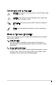
3.1 Installing an operating system The barebone system supports Windows® 2000/XP operating systems (OS). Always install the latest OS version and corresponding updates so you can maximize the features of your hardware. Because motherboard settings and hardware options vary, use the setup procedures presented in this chapter for general reference only. Refer to your OS documentation for more information. 3.2 Powering up The system power button is located on the front panel.
3.3.1 Running the support CD To begin using the support CD, place the CD in your optical drive. The CD automatically displays the Drivers menu if Autorun is enabled in your computer. Click an item to install Click an icon to display other information If Autorun is NOT enabled in your computer, browse the contents of the support CD to locate the file ASSETUP.EXE from the BIN folder. Double-click the ASSETUP.EXE to run the CD. 3.3.
SoundMAX ADI Audio Driver Installs the SoundMAX® AC`97 audio driver. Realtek RTL8111b 10/100/1000M LAN Driver Installs the Realtek® 10/100/1000M LAN Driver. 3.3.3 Utilities menu The Utilities menu shows the applications and other software that the motherboard supports. ASUS InstAll - Installation Wizard for Utilities Allows you to easily install all bundled utilities for this motherboard.
ASUS Update Installs the ASUS Update that allows you to update the motherboard BIOS and drivers. This utility requires an Internet connection either through a network or an Internet Service Provider (ISP). See page 5-8 for details. Adobe Acrobat Reader V7.0 The Acrobat® Acrobat Reader® software is for viewing files saved in Portable Document Format (PDF). ASUS Screensaver Bring life to your idle screen by installing the ASUS Screensaver. 3.3.
3- Chapter 3: Starting up
This chapter gives information about the motherboard that comes with the system. This chapter includes the motherboard layout, jumper settings, and connector locations.
4.1 Introduction The motherboard comes already installed in the ASUS T3-P5G965 system. This chapter provides technical information about the motherboard for future upgrades or system reconfiguration. 4.2 Motherboard layout 26.7cm(10.5in) SPI_J1 CLRTC PCI1 VT6308P Super I/O SB_PWR PCIEX16 BUZZER FRONT_CON CR2032 3V Lithium Cell CMOS Power CD AUDIO AD19888 RTM867N SPDIF_OUT SATA1 SATA2 22.4cm(8.
4.3 1. Jumpers Clear RTC RAM (CLRTC) This jumper allows you to clear the Real Time Clock (RTC) RAM in CMOS. You can clear the CMOS memory of date, time, and system setup parameters by erasing the CMOS RTC RAM data. The onboard button cell battery powers the RAM data in CMOS, which include system setup information such as system passwords. To erase the RTC RAM: 1. Turn OFF the computer and unplug the power cord. 2. Remove the onboard battery. 3. Move the jumper cap from pins 1-2 (default) to pins 2-3.
2. USB device wake-up (3-pin USBPW12, USBPW34, USBPW910) Set these jumpers to +5V to wake up the computer from S1 sleep mode (CPU stopped, DRAM refreshed, system running in low power mode) using the connected USB devices. Set to +5VSB to wake up from S3 and S4 sleep modes (no power to CPU, DRAM in slow refresh, power supply in reduced power mode). USBPW910 R USBPW34 USBPW12 USB device Wake up 3.
4.4 Connectors This section describes and illustrates the connectors on the motherboard. 1. CPU fan connector (4-pin CPU_FAN) The fan connector supports the proprietary CPU fan. Connect the fan cable to the fan connector on the motherboard, making sure that the black wire of each cable matches the ground pin of the connector. CPU_FAN R GND CPU FAN PWR CPU FAN PWM CPU FAN IN CPU Fan Connector Do not forget to connect the fan cable to the fan connector.
3. RAID connector (40-1 pin PRI_RAID) This connector is for an Ultra DMA 100/66 signal cable. The Ultra DMA 100/66 signal cable has three connectors: a blue connector for the primary RAID connector on the motherboard, a black connector for an Ultra DMA 100/66 IDE slave device (optical drive/hard disk drive), and a gray connector for an Ultra DMA 100/66 RAID master device (hard disk drive). Refer to the hard disk documentation for the jumper settings.
4. Serial ATA connectors (7-pin SATA1, SATA2, SATA3) These connectors are for the Serial ATA signal cables for Serial ATA hard disk drives. SATA3 GND RSATA_RXN2 RSATA_RXP2 GND RSATA_TXN2 RSATA_TXP2 GND GND RSATA_RXN1 RSATA_RXP1 GND RSATA_TXN1 RSATA_TXP1 GND GND RSATA_RXN3 RSATA_RXP3 GND RSATA_TXN3 RSATA_TXP3 GND R SATA1 SATA2 SATA Connectors When using the connectors in Standard IDE mode, connect the primary (boot) hard disk drive to the SATA1/2 connector.
5. Digital audio connector (4-1 pin SPDIF_OUT) SPDIFOUT GND +5V This connector is for an additional Sony/Philips Digital Interface (S/PDIF) port(s). Connect the S/PDIF Out cable to this connector, then connect to the S/PDIF module of the system chassis. SPDIF_OUT R Digital Audio Connector 6.
Chapter 5 BIOS setup This chapter tells how to change system settings through the BIOS Setup menus and describes the BIOS parameters.
5.1 Managing and updating your BIOS The following utilities allow you to manage and update the motherboard Basic Input/Output System (BIOS) setup. 1. ASUS EZ Flash 2 (Updates the BIOS using a floppy disk, USB Flash, or the motherboard support CD during POST.) 2. ASUS AFUDOS (Updates the BIOS using a bootable floppy disk in DOS mode.) 3. ASUS CrashFree BIOS 2 (Updates the BIOS using a bootable floppy disk or the motherboard support CD when the BIOS file fails or gets corrupted.) 4.
5.1.1 ASUS EZ Flash 2 utility The ASUS EZ Flash 2 feature allows you to update the BIOS without having to go through the long process of booting from a floppy disk and using a DOS‑based utility. The EZ Flash 2 utility is built-in the BIOS chip so it is accessible by pressing + during the Power-On Self-Test (POST). To update the BIOS using EZ Flash 2: 1. Visit the ASUS website (www.asus.com) to download the latest BIOS file for the motherboard. 2.
5.1.2 AFUDOS utility The AFUDOS utility allows you to update the BIOS file in DOS environment using a bootable floppy disk with the updated BIOS file. This utility also allows you to copy the current BIOS file that you can use as backup when the BIOS fails or gets corrupted during the updating process. Copying the current BIOS To copy the current BIOS file using the AFUDOS utility: • Make sure that the floppy disk is not write-protected and has at least 600 KB free space to save the file.
Updating the BIOS file To update the BIOS file using the AFUDOS utility: 1. Visit the ASUS website (www.asus.com) and download the latest BIOS file for the motherboard. Save the BIOS file to a bootable floppy disk. Write the BIOS filename on a piece of paper. You need to type the exact BIOS filename at the DOS prompt. 2. Copy the AFUDOS utility (afudos.exe) from the motherboard support CD to the bootable floppy disk you created earlier. 3.
5. The utility returns to the DOS prompt after the BIOS update process is completed. Reboot the system from the hard disk drive. A:\>afudos /iP5BBN.ROM AMI Firmware Update Utility - Version 1.19(ASUS V2.07(03.11.24BB)) Copyright (C) 2003 American Megatrends, Inc. All rights reserved. WARNING!! Do not turn off power during flash BIOS Reading file ..... done Reading flash .... done Search bootblock version Advance Check......... Erasing flash ..... done Writing flash ..... done Verifying flash ...
3. The utility displays the following message and automatically checks the floppy disk for the original or updated BIOS file. Bad BIOS checksum. Starting BIOS recovery... Checking for floppy... When found, the utility reads the BIOS file and starts flashing the corrupted BIOS file. Bad BIOS checksum. Starting BIOS recovery... Checking for floppy... Floppy found! Reading file “P5BBN.ROM”. Completed. Start flashing...
DO NOT shut down or reset the system while updating the BIOS! Doing so can cause system boot failure! 4. Restart the system after the utility completes the updating process. The recovered BIOS may not be the latest BIOS version for this motherboard. Visit the ASUS website (www.asus.com) to download the latest BIOS file. 5.1.4 ASUS Update utility The ASUS Update is a utility that allows you to manage, save, and update the motherboard BIOS in Windows® environment.
Updating the BIOS through the Internet To update the BIOS through the Internet: 1. Launch the ASUS Update utility from the Windows® desktop by clicking Start > Programs > ASUS > ASUSUpdate > ASUSUpdate. The ASUS Update main window appears. 2. Select Update BIOS from the Internet option from the drop‑down menu, then click Next. ASUS T3-P5G965 3. Select the ASUS FTP site nearest you to avoid network traffic, or click Auto Select. Click Next.
4. From the FTP site, select the BIOS version that you wish to download. Click Next. 5. Follow the screen instructions to complete the update process. The ASUS Update utility is capable of updating itself through the Internet. Always update the utility to avail all its features. Updating the BIOS through a BIOS file To update the BIOS through a BIOS file: 5-10 1. Launch the ASUS Update utility from the Windows® desktop by clicking Start > Programs > ASUS > ASUSUpdate > ASUSUpdate.
5.2 BIOS setup program This motherboard supports a programmable Low-Pin Count (LPC) chip that you can update using the provided utility described in section “4.1 Managing and updating your BIOS.” Use the BIOS Setup program when you are installing a motherboard, reconfiguring your system, or prompted to“Run Setup.” This section explains how to configure your system using this utility. Even if you are not prompted to use the Setup program, you can change the configuration of your computer in the future.
5.2.1 BIOS menu screen Menu items Menu bar Configuration fields System Time System Date [11:51:19] [Mon 05/15/2006] SATA 1 SATA 2 SATA 3 :[Not Detected] :[Not Detected] :[Not Detected] General help Use [ENTER], [TAB] or [SHIFT-TAB] to select a field. Use [+] or [-] to configure the System time. IDE Configuration System Information Sub-menu items 5.2.
5.2.4 Menu items The highlighted item on the menu bar displays the specific items for that menu. For example, selecting Main shows the Main menu items. The other items (Advanced, Power, Boot, Tools and Exit) on the menu bar have their respective menu items. 5.2.5 System Time [16:37:21] System Date [Wed,10/20/2004] Legacy Diskette A [1.44M, 3.
5.3 Main menu When you enter the BIOS Setup program, the Main menu screen appears, giving you an overview of the basic system information. Refer to section “5.2.1 BIOS menu screen” for information on the menu screen items and how to navigate through them. System Time [16:37:21] System Date [Wed,10/20/2004] SATA 1 SATA 2 SATA 3 :[Not Detected] :[Not Detected] :[Not Detected] Use [ENTER], [TAB] or [SHIFT-TAB] to select a field. Use [+] or [-] to configure the System time.
5.3.3 SATA1, SATA2, and SATA3 While entering Setup, the BIOS automatically detects the presence of IDE devices. There is a separate sub-menu for each IDE device. Select a device item then press to display the IDE device information.
PIO Mode [Auto] Selects the PIO mode. Configuration options: [Auto] [0] [1] [2] [3] [4] DMA Mode [Auto] Selects the DMA mode. Configuration options: [Auto] [SWDMA0] [SWDMA1] [SWDMA2] [MWDMA0] [MWDMA1] [MWDMA2] [UDMA0] [UDMA1] [UDMA2] [UDMA3] [UDMA4] [UDMA5] SMART Monitoring [Auto] Sets the Smart Monitoring, Analysis, and Reporting Technology. Configuration options: [Auto] [Disabled] [Enabled] 32Bit Data Transfer [Enabled] Enables or disables 32-bit data transfer.
5.3.5 System Information This menu gives you an overview of the general system specifications. The BIOS automatically detects the items in this menu. AMIBIOS Version : 0403 Build Date : 10/16/06 Processor Type Speed Count : Genuine Intel(R) CPU 3.80 GHz : 3800 MHz : 1 System Memory Available : 504 MB AMI BIOS Displays the auto-detected BIOS information. Processor Displays the auto-detected CPU specification. System Memory Displays the auto-detected system memory. 5.
5.4.1 USB Configuration The items in this menu allow you to change the USB-related features. Select an item then press to display the configuration options. USB Configuration Module Version - 2.24.0-11.4 USB Devices Enabled: None USB 1.1 Controller [Enabled] USB 2.0 Controller [Enabled] Legacy USB Support [Enabled] USB 2.0 Controller Mode [HiSpeed] BIOS EHCI Hand-off [Enabled] The Module Version and USB Devices Enabled items show the auto-detected values.
5.4.2 CPU Configuration The items in this menu show the CPU-related information that the BIOS automatically detects. Configure advanced CPU settings Module Version: 3C.0E Manufacturer: Intel Brand String: Genuine Intel(R) CPU 3.80GHz Frequency : 3.
Hyper Threading Technology [Enabled] Enables or disables the processor Hyper-Threading Technology. Configuration options: [Disabled] [Enabled] Intel(R) SpeedStep(tm) Technology [Automatic] Allows you to use the Enhanced Intel® SpeedStep® Technology. When set to [Enabled], you can adjust the system power settings in the operating system to use the EIST feature. Set this item to [Disabled] if you do not want to use the EIST. Configuration options: [Automatic] [Disabled] 5.4.
Memory Remap Feature [Enabled] Allows you to enable or disable Memory Remap Feature. Configuration options: [Disabled] [Enabled] Configure DRAM Timing by SPD [Enabled] Allows you to Configure DRAM Timing by SPD. Configuration options: [Disabled] [Enabled] Initiate Graphic Adapter [PEG/IGD] Allows you to select Initiate Graphic Adapter.
South Bridge Configuration South Bridge Chipset Configuration HD Audio Controller [Enabled] CPU Throttling Duty [Disable] HD Audio Controller [Enabled] Allows you to enable or disable high definition audio controller. Configuration options: [Disabled] [Enabled] CPU Throttling Duty [Disable] Allows you to configure CPU Throttling Duty. Configuration options: [Disable] [25%] [50%] [70%] 5.4.
OnBoard PCIE LAN [Enabled] Allows you to enable or disable the onboard PCI Express LAN controller. Configuration options: [Enabled] [Disabled] LAN Option ROM [Disabled] Allows you to enable or disable the option ROM in the onboard PCI Express Gigabit LAN controller. This item appears only when the Onboard PCIEX GbE LAN item is set to Enabled. Configuration options: [Disabled] [Enabled] JMicron SATA/PATA Controller [Enabled] Allows you to enable or disable the JMicron SATA/PATA controller.
Plug and Play O/S [No] When set to [No], BIOS configures all the devices in the system. When set to [Yes] and if you install a Plug and Play operating system, the operating system configures the Plug and Play devices not required for boot. Configuration options: [No] [Yes] PCI Latency Timer [64] Allows you to select the value in units of PCI clocks for the PCI device latency timer register.
5.5 Power menu The Power menu items allow you to change the settings for the ACPI and Advanced Power Management (APM). Select an item then press to display the configuration options. Suspend Mode [Auto] Repost Video on S3 Resume [Disabled] ACPI 2.0 Support [Disabled] ACPI APIC Support [Enabled] APM Configuration Hardware Monitor 5.5.1 Suspend Mode [Auto] Allows you to select the Advanced Configuration and Power Interface (ACPI) state to be used for system suspend.
5.5.5 APM Configuration APM Configuration Restore on AC Power Loss [Power Off] Power On By RTC Alarm [Disabled] Power On By External Modems [Disabled] Power On By PCI Devices [Disabled] Power On By PCIE Devices [Disabled] Power On By PS/2 Keyboard [Disabled] Power On By PS/2 Mouse [Disabled] Restore on AC Power Loss [Power Off] When set to Power Off, the system goes into off state after an AC power loss. When set to Power On, the system goes on after an AC power loss.
The computer cannot receive or transmit data until the computer and applications are fully running. Thus, connection cannot be made on the first try. Turning an external modem off and then back on while the computer is off causes an initialization string that turns the system on. Power On By PS/2 Keyboard [Disabled] Allows you to use specific keys on the keyboard to turn on the system. This feature requires an ATX power supply that provides at least 1A on the +5VSB lead.
VCORE Voltage, 3.3V Voltage, 5V Voltage, 12V Voltage The onboard hardware monitor automatically detects the voltage output through the onboard voltage regulators. CPU Q-Fan Control [Enabled] Allows you to enable or disable the ASUS Q-Fan feature that smartly adjusts the fan speeds for more efficient system operation. When this field is set to [Enabled], the three succeeding items appear. Configuration options: [Disabled] [Enabled] 5.
5.6.2 Boot Settings Configuration Boot Settings Configuration Quick Boot [Enabled] Full Screen Logo [Enabled] AddOn ROM Display Mode [Force BIOS] Bootup Num-Lock [On] PS/2 Mouse Support [Auto] Wait For ‘F1’ If Error [Enabled] Hit ‘DEL’ Message Display [Enabled] Interrupt 19 Capture [Disabled] Allows BIOS to skip certain tests while booting. This will decrease the time needed to boot the system.
Hit ‘DEL’ Message Display [Enabled] When set to Enabled, the system displays the message “Press DEL to run Setup” during POST. Configuration options: [Disabled] [Enabled] Interrupt 19 Capture [Disabled] When set to [Enabled], this function allows the option ROMs to trap Interrupt 19. Configuration options: [Disabled] [Enabled] 5.6.3 Security The Security menu items allow you to change the system security settings. Select an item then press to display the configuration options.
If you forget your BIOS password, you can clear it by erasing the CMOS Real Time Clock (RTC) RAM. See section “4.3 Jumpers” for information on how to erase the RTC RAM. After you have set a supervisor password, the other items appear to allow you to change other security settings. Security Settings Supervisor Password User Password : Installed : Not Installed to change password. again to disabled password.
Password Check [Setup] When set to [Setup], BIOS checks for user password when accessing the Setup utility. When set to [Always], BIOS checks for user password both when accessing Setup and booting the system. Configuration options: [Setup] [Always] 5.7 Tools menu ASUS EZ Flash 2 ASUS O.C.Profile 5.7.1 ASUS EZ Flash 2 Allows you to run ASUS EZ Flash 2. When you press , a confirmation message appears.
5.7.2 ASUS O.C. Profile This item allows you to store or load multiple BIOS settings. BIOS SETUP UTILITY Tools O.C. PROFILE Configuration O.C. Profile 1 Status O.C. Profile 2 Status : Not Installed : Not Installed Save to Profile 1 Load from Profile 1 Save to Profile 2 Load from Profile 2 Start O.C. Profile Enter F1 F10 ESC Select Screen Select Item Go to Sub Screen General Help Save and Exit Exit v02.58 (C)Copyright 1985-2006, American Megatrends, Inc.
5.8 Exit menu The Exit menu items allow you to load the optimal or failsafe default values for the BIOS items, and save or discard your changes to the BIOS items. Exit Options Exit & Save Changes Exit & Discard Changes Discard Changes Load Setup Defaults Pressing does not immediately exit this menu. Select one of the options from this menu or from the legend bar to exit.