RS100-E5-PI2 1U Rackmount Server User Guide
E3648 First Edition V1 March 2008 Copyright 2008© ASUSTeK COMPUTER INC. All Rights Reserved. No part of this manual, including the products and software described in it, may be reproduced, transmitted, transcribed, stored in a retrieval system, or translated into any language in any form or by any means, except documentation kept by the purchaser for backup purposes, without the express written permission of ASUSTeK COMPUTER INC. (“ASUS”).
Contents Contents....................................................................................................... iii Notices......................................................................................................... vii Safety information..................................................................................... viii About this guide.......................................................................................... ix Chapter 1: Product introduction 1.
Contents 3.2 3.3 3.1.1 Attaching the rack ears.................................................... 3-2 3.1.2 Attaching the rails to the rack........................................... 3-3 Rackmount bracket kit (Optional)................................................ 3-7 3.2.1 Attaching the long rack ears............................................ 3-7 3.2.2 Attaching the server to the rack cabinet........................... 3-8 Front panel cover kit (Optional)...................................
Contents 5.3.6 5.4 5.5 5.6 5.7 5.4.1 USB Configuration......................................................... 5-16 5.4.2 Remote Access Configuration........................................ 5-17 5.4.3 Trusted Computing......................................................... 5-18 5.4.4 MPS Configuration......................................................... 5-18 5.4.5 CPU Configuration......................................................... 5-19 5.4.6 Chipset Configuration................
Contents 6.3.2 Initializing the virtual drives............................................ 6-18 6.3.3 Rebuilding failed drives.................................................. 6-23 6.3.4 Checking the drives for data consistency...................... 6-25 6.3.5 Deleting a RAID configuration........................................ 6-28 6.3.6 Selecting the boot drive from a RAID set....................... 6-29 6.3.7 Enabling the WriteCache...............................................
Notices Federal Communications Commission Statement This device complies with Part 15 of the FCC Rules. Operation is subject to the following two conditions: • This device may not cause harmful interference, and • This device must accept any interference received including interference that may cause undesired operation. This equipment has been tested and found to comply with the limits for a Class B digital device, pursuant to Part 15 of the FCC Rules.
Safety information Electrical Safety • Before installing or removing signal cables, ensure that the power cables for the system unit and all attached devices are unplugged. • To prevent electrical shock hazard, disconnect the power cable from the electrical outlet before relocating the system. • When adding or removing any additional devices to or from the system, ensure that the power cables for the devices are unplugged before the signal cables are connected.
About this guide Audience This user guide is intended for system integrators, and experienced users with at least basic knowledge of configuring a server. Contents This guide contains the following parts: 1. Chapter 1: Product Introduction This chapter describes the general features of the server, including sections on front panel and rear panel specifications. 2.
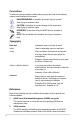
Conventions To make sure that you perform certain tasks properly, take note of the following symbols used throughout this manual. DANGER/WARNING: Information to prevent injury to yourself when trying to complete a task. CAUTION: Information to prevent damage to the components when trying to complete a task. IMPORTANT: Instructions that you MUST follow to complete a task. NOTE: Tips and additional information to help you complete a task.
This chapter describes the general features of the chassis kit. It includes sections on front panel and rear panel specifications.
1.1 System package contents Check your system package for the following items. Model Name RS100-E5-PI2 Chassis ASUS R09 1U Rackmount Chassis Motherboard ASUS P5BV-M/RS100-E5 Server Board Component 1 x 220W 80+ Single Power Supply 2 x SATA Cables 1 x PCI Express x16 Riser Card (x8 link) 1 x Front I/O Board (ASUS FPB-R9) 1 x USB Board (ASUS USB-R9) 2 x System Fans (2 x 40x28) Accessories 1 x CPU Heatsink 1 x RS100-E5-PI2 User’s Guide 1 x ASUS ASWM 2.
1.3 System specifications The ASUS RS100-E5-PI2 is a 1U barebone server system featuring the ASUS P5BV-M/RS100-E5 server board. The server supports Intel® LGA775 Xeon® 3300/3200/3100/3000 Series processors with EM64T technology, plus other latest technologies through the chipsets onboard. Model Name Processor / System Bus Core Logic ASUS Features Memory Expansion Slots Smart Fan ASWM2.
Anti-virus Software Hardware Management Solution Software Dimension (D x W x H) Net Weight Kg (CPU, DRAM & HDD not inclu ded) Power Supply Environment CA® eTrust™ anti-virus software (Optional) SM-Bus/ASMB3-SOL or ASMB3-iKVM (Optional) ASUS ASWM 2.0® 381mm x 430mm x 43.4mm 6.2 Kg 220W 80+ PFC PSU Operation temperature: 10°C ~ 35°C / Non operation temperature: -40°C ~ 70°C Non operation humidity: 20% ~ 90% ( Noncondensing) *Specifications are subject to change without notice.
1.4 Front panel features The barebone server displays a simple yet stylish front panel with easily accessible features. The power and reset buttons, LED indicators, optical drive, and two USB ports are located on the front panel. Refer to section 1.6.1 Front panel LEDs for the LED descriptions. USB 2.0 ports 1.5 HDD Access LED LAN2 LED LAN1 LED Power LED Optical drive Power button Reset button Rear panel features The rear panel includes the expansion slots, and system power socket.
1.6 Internal features The barebone server includes the basic components as shown. 1 4 3 2 6 5 1-6 1. PCI Express x16 Riser Card (at x8 link) 2. Chassis fans (x 2) 3. ASUS P5BV-M/RS100-E5 Server Board 4. Power supply 5. HDD tray 2 (hidden) and Slim-type Optical drive (optional) 6. HDD tray 1 • The barebone server does not include a floppy disk drive. connect a USB floppy disk drive to any of the USB ports on the front or rear panel if you need to use a floppy disk.
1.7 LED information 1.7.1 Front panel LEDs HDD Access LED Power LED LAN2 LED LAN1 LED LED Icon Power LED HDD Access LED LAN LEDs 1.7.
1-8 Chapter 1: Product introduction
This chapter lists the hardware setup procedures that you have to perform when installing or removing system components.
2-2 2.1 Chassis cover 2.1.1 Removing the cover 1. Use a Phillips screwdriver to remove the screw on the top cover. 2. Firmly hold the cover and slide it toward the rear panel for about half an inch until it is disengaged from the chassis. 3. Lift the cover from the chassis.
2.1.2 1. Installing the cover Position the cover on top of the chassis with the hooks aligned to the side tabs of the chassis. Side tabs 2. Slide the cover toward the front until it snaps in place.
3. 2-4 Secure the cover with one screw.
2.2 Motherboard information Place eight (8) screws into the holes indicated by circles to secure the motherboard to the chassis. Refer to Chapter 4: Motherboard Information for detailed Information. ® Place this side towards the rear of the chassis P5BV-M/RS100-E5 Make sure to unplug the power cord before installing or removing the motherboard. Failure to do so can cause you physical injury and damage motherboard components.
2.3 Central Processing Unit (CPU) The motherboard comes with a surface mount LGA775 socket designed for the Intel® Xeon® 3300/3200/3100/3000 series processors in the 775-land package. 2.3.1 • Upon purchase of the motherboard, make sure that the PnP cap is on the socket and the socket contacts are not bent. Contact your retailer immediately if the PnP cap is missing, or if you see any damage to the PnP cap/socket contacts/motherboard components.
2. Press the load lever with your thumb (A), then move it to the left (B) until it is released from the retention tab. Retention tab A PnP cap Load lever B This side of the socket box should face you. To prevent damage to the socket pins, do not remove the PnP cap unless you are installing a CPU. 3. Lift the load lever in the direction of the arrow to a 135º angle. 4.
The CPU fits in only one correct orientation. DO NOT force the CPU into the socket to prevent bending the connectors on the socket and damaging the CPU! 6. Close the load plate (A), then push the load lever (B) until it snaps into the retention tab. A B The motherboard supports Intel® Xeon® 3300/3200/3100/3000 series processors with the Intel® Enhanced Memory 64 Technology (EM64T), and Enhanced Intel SpeedStep® Technology (EIST). Refer to the Appendix for more information on these CPU features. 2.3.
2. Tighten the screws. 3. Peel the adhesive cover of the heatsink plastic cover and evenly attach to heatsink. Heatsink plastic cover The heatsink plastic cover ensures the linear airflow between the heatsink and chassis fans.
2.4 System memory 2.4.1 Overview The motherboard comes with four Double Data Rate 2 (DDR2) Dual Inline Memory Modules (DIMM) sockets. A DDR2 module has the same physical dimensions as a DDR DIMM but has a 240-pin footprint compared to the 184-pin DDR DIMM. DDR2 DIMMs are notched differently to prevent installation on a DDR DIMM socket.
2.4.3 Installing a DIMM Unplug the power supply before adding or removing DIMMs or other system components. Failure to do so can cause severe damage to both the motherboard and the components. 2 To install a DIMM: 1. Unlock a DIMM socket by pressing the retaining clips outward. 2. Align a DIMM on the socket such that the notch on the DIMM matches the break on the socket. 3. Firmly insert the DIMM into the socket until the retaining clips snap back in place and the DIMM is properly seated.
2.5 Replaceable components You may need to replace defective components or remove previously installed system components when installing or removing system devices. This section tells how to install or remove the following components: 1. Chassis fans 2. Serial ATA hard disk drives 3. Optical disk drive 2.5.1 Installing the chassis fans To install the chassis fans: 1. Locate the chassis fan plate on the chassis. Chassis fans Chassis fan plate 2. 2-12 Insert the chassis fans into the fan plate.
3. Secure the chassis fans with two screws. Chassis fan screws 4. Connect the chassis fans cable to the onboard fan connectors labeled CPU_FAN1 and FRNT_FAN1. Refer to the illustration below for the location of CPU_FAN1 and FRNT_FAN1 connectors. GND FANPWR2 FAN PWM CPU_FAN1 ® P5BV-M/RS100-E5 FRNT_FAN1 FAN PWM FANPWR2 GND P5BV-M/RS100-E5 CPU/Chassis Fan Connectors 2.5.2 Installing Serial ATA drives You can install up to two (2) Serial ATA hard disk drives to the system.
2. Connect the Serial ATA signal cable and ATX power connectors. Use the L-type Serial ATA connector to connect to the hard drive. SATA L-type connector ATX power connector SATA signal cable 2-14 3. Place the Serial ATA drive into the drive bay matching the four screw holes with the holes on the disk drive. 4. Secure the hard drive with four screws.
Connect the other end of the Serial ATA signal connector to the onboard SATA connector labeled SATA1. Refer to illustration below for the location of SATA1 connector. ® P5BV-M/RS100-E5 SATA1 GND RSATA_RXN1 RSATA_RXP1 GND RSATA_TXN1 RSATA_TXP1 GND 5. P5BV-M/RS100-E5 SATA1 Connector To install secondary Serial ATA drive: 1. If you have an ODD installed, remove the ODD bay first before you install a secondary SATA disk drive.
4. Insert the Serial ATA drive into the drive plate as shown. 5. Secure the hard drive with four screws. 6. Connect the Serial ATA signal cable and ATX power connectors. Use the L-type Serial ATA connector to connect to the hard drive. SATA L-type connector ATX power connector SATA signal cable Connect the other end of the Serial ATA signal connector to the onboard SATA connector labeled SATA3. ® P5BV-M/RS100-E5 SATA3 GND RSATA_RXN1 RSATA_RXP1 GND RSATA_TXN1 RSATA_TXP1 GND 7.
2.5.3 Installing optical disk drive (ODD) To install ODD: 1. Connect the 80-pin IDE cable blue connector to the IDE connector onboard. 2. Slide in the optical disk drive into the drive slot as shown. Optical disk drive slot 3. Align the screw hole of the ODD bracket with the screw hole on the SATA drive bracket, then secure it with a screw.
4. Place the ODD side bracket to the ODD, matching the two connectors of the bracket with the holes on the side of the ODD. Bracket connectors ODD side bracket 2-18 5. Secure the ODD side bracket to the Serial SATA drive bracket with a screw. 6. Connect the 80-pin IDE cable black connector and 4-pin ATX power connector to the IDE connector and power connector at the rear of the optical disk drive.
This chapter describes how to install the optional components and devices into the barebone server.
3.1 Rackmount rail kit items The rackmount rail kit contains two pairs of rails (one pair for each side of the server system), six (6) pieces of inner rail screws, and two (2) pieces of rack screws. Outer rails Inner rails Rack screws 3.1.1 Inner rail screws Attaching the rack ears The bundled rack ears serve as handle when inserting or pulling the server from a rack cabinet. To attach rack ears: 1. Prepare the bundled pair of rack ears and set of eight (8) screws.
2. Locate the four screw holes on each front-side of the chassis. Select one side for installation. 3. Get one rack ear and match the four screw holes to the screw holes on the chassis. Orient the rack ear as shown. 4. Secure the rack ear to the chassis with four screws. 5. Repeat steps 2 - 4 to attach the other rack ear. 3.1.2 Attaching the rails to the rack To attach the rack rails: 1. Attach the inner rail to the correspoding side of the chassis and secure with three inner rail screws.
2. Attach the second inner rail to the other side of the chassis and secure with three inner rail screws. 3. Select one unit of space (1U) on the rack where you wish to install the server. 4. Place three (3) nuts on the front and three at the back. Do the same to the corresponding side of the rack. Nuts 3-4 5. Adjust the length of the outer rail to fit the length of the rack cabinet, then fasten the two screws. 6. Secure the outer rail with two screws at the front and rear of the rack cabinet .
8. Firmly hold the server on both sides. Slide the latches on the inner rack rails to the direction indicated below. Hold the latches, and insert the rear side of the server to the front end of the outer rack rail. Make sure that the inner rails are properly aligned with the outer rails.
9. Carefully push the server all the way to the back until the front panel fits the front end of the rack. 10. Secure the server to the rack with one rack screw at one side. Secure the other side as well.
3.2 Rackmount bracket kit (Optional) The rackmount bracket kit provides a convenient and economical way to install the server to the rack cabinet. 3.2.1 Attaching the long rack ears The long rack ears are used to support the server system in a rack cabinet. To attach the long rack ears: 1. Prepare the pair of long rack ears and set of twelve (12) screws. 2. Locate the six screw holes on each front-side of the chassis.Select one side for installation. 3.
3.2.2 Attaching the server to the rack cabinet 1. Select one unit of space (1U) on the rack where you wish to install the server. 2. Place three (3) nuts on the front and three at the back. Do the same to the corresponding side of the rack. Nuts 3-8 3. Carefully place the server to the desired position on the rack. 4. Secure the server to the rack with two rack screws at one side. Secure the other side as well.
3.3 Front panel cover kit (Optional) The front panel cover kit provides a convenient way to protect and decorate the front server panel. 1. Prepare the bundled pair of front panel connectors and a set of twelve (12) screws. 2. Secure the front panel connector to the rack ear. 3. Secure the rack ear to the chassis with four screws. 4. Repeat steps 2 - 3 to attach the other rack ear.
3-10 5. Align the front cover to the preinstalled front cover connectors. 6. Carefully attach the front cover to the front cover connectors.
This chapter gives inforamtion about the motherboard that comes with the server. This chapter includes the motherboard layout, jumper settings, and connector locations.
4.1 Motherboard overview 24.5cm (9.
Layout contents Slots 1. 2. CPU socket DDR2 DIMM slots Page 2-6 2-10 Jumpers 1. 2. 3. 4. Clear RTC RAM (CLRTC1) RAID controller selection (3-pin RAID_SEL1) Force BIOS recovery setting (3-pin RECOVERY1) Fan mode setting (3-pin CPUFAN_SET1 and CHAFAN_SET1) Page 4-4 4-5 4-5 4-6 Rear panel connectors 1. PS/2 mouse port (green) 2. LAN port for ASMB3 iKVM 3. LAN1 (RJ-45) port 4. LAN2 (RJ-45) port w/i ASF function 5. VGA port 6. Serial (COM1) port 7. USB 2.0 ports 1 and 2 8.
4.2 1. Jumpers Clear RTC RAM (CLRTC) This jumper allows you to clear the Real Time Clock (RTC) RAM in CMOS. You can clear the CMOS memory of date, time, and system setup parameters by erasing the CMOS RTC RAM data. The onboard button cell battery powers the RAM data in CMOS, which include system setup information such as system passwords. To erase the RTC RAM: 1. Turn OFF the computer and unplug the power cord. 2. Move the jumper cap from pins 1-2 (default) to pins 2-3.
2. RAID controller selection (3-pin RAID_SEL1) This jumper allows you to select the RAID configuration utility to use when you create disk arrays. Place the jumper caps over pins 1-2 if you want to use the LSI Logic Embedded SATA RAID Setup Utility (default); otherwise, place the jumper caps to pins 2-3 to use the Intel® Matrix Storage Manager. ® P5BV-M/RS100-E5 RAID_SEL1 1 2 LSI RAID ROM (Default) 2 3 INTEL RAID ROM P5BV-M/RS100-E5 RAID_SEL1 Setting 3.
4. Fan mode setting (3-pin CPUFAN_SET1; CHAFAN_SET1) These jumpers allow you to connect either a 3-pin or a 4-pin fan cable plug to the CPU fan or Chasis fan connectors Set these jumpers to pins 1-2 Short PWM mode if you are using a 4-pin fan cable plug, or to pins 2‑3 Short DC mode if you are using a 3-pin plug.
4.3 Connectors 4.3.1 Rear panel connectors 2 1 8 6 7 5 4 3 1. PS/2 mouse port (green). This port is for a PS/2 mouse. 2. LAN port for ASMB3 IKVM. 3. LAN1 (RJ-45) port. This port allows Gigabit connection to a Local Area Network (LAN) through a network hub. Refer to the table below for the LAN port LED indications. 4. LAN2 (RJ-45) port ����������������� w/i ASF function�. This port allows Gigabit connection to a Local Area Network (LAN) through a network hub.
4.3.2 1. Internal connectors Floppy disk drive connector (34-1 pin FLOPPY1) This connector is for the provided Floppy Disk Drive (FDD) signal cable. Insert one end of the cable to this connector, then connect the other end to the signal connector at the back of the floppy disk drive. ® P5BV-M/RS100-E5 FLOPPY1 PIN1 NOTE: Orient the red markings on the floppy ribbon cable to PIN 1.
2. ICH7R primary IDE connector (40-1 pin PRI_IDE1) This connector is for an Ultra DMA 100/66 signal cable. The Ultra DMA 100/66 signal cable has three connectors: a blue connector for the primary IDE connector on the motherboard, a black connector for an Ultra DMA 100/66 IDE slave device (optical drive/hard disk drive), and a gray connector for an Ultra DMA 100/66 IDE master device (hard disk drive).
3. Serial ATA connectors (7-pin SATA1-4) These connectors are for the Serial ATA signal cables for Serial ATA hard disk drives. If you installed Serial ATA hard disk drives, you can create a RAID 0 and RAID 1 configuration using the Intel® Matrix Storage Technology or the LSI MegaRAID® utility embedded in the Intel® ICH7R Southbridge.
4. Hard disk activity LED connector (4-pin HDLED1) This connector supplies power to the hard disk activity LED. The read or write activities of any device connected to the SCSI connectors or the SATA connectors cause this LED to light up. HDLED1 ® P5BV-M/RS100-E5 NC ADD_IN_CARD_ACT# ADD_IN_CARD_ACT# NC 1 P5BV-M/RS100-E5 Hard Disk Activity LED Connector 5. USB connector (10-1 pin USB34) This connector is for USB 2.0 ports. This USB connector complies with USB 2.
6. Serial port connector (10-1 pin COM2) This connector is for a serial (COM) port. Connect the serial port module cable to this connector, then install the module to a slot opening at the back of the system chassis. The serial port module is purchased separately. ® P5BV-M/RS100-E5 COM2 PIN 1 P5BV-M/RS100-E5 COM2 Port Connector 7. CPU and system fan connectors (4-pin CPU_FAN1, FRNT_FAN1, REAR_FAN1) The fan connectors support cooling fans of 350 mA ~ 740 mA (8.88 W max.) or a total of 2.1 A ~ 4.
8. ATX power connectors (24-pin EATXPWR1, 4-pin ATX12V1) These connectors are for SSI power supply plugs. The power supply plugs are designed to fit these connectors in only one orientation. Find the proper orientation and push down firmly until the connectors completely fit.
9. System panel connector (20-1 pin PANEL1) This connector supports several chassis-mounted functions. • System power LED (Green 3-pin PLED) This 3-pin connector is for the system power LED. Connect the chassis power LED cable to this connector. The system power LED lights up when you turn on the system power, and blinks when the system is in sleep mode. • Message LED (Brown 2-pin MLED) This connector is for the message LED cable that connects to the front message LED.
10. System panel auxiliary connector (20-2 pin AUX_PANEL1) This connector supports several server system functions. AUX_PANEL1 +5VSB 3 • 2 CASEOPEN GND LOCATORLED1+ LOCATORLED1LOCATORBTN# GND LOCAT ORLED2LOCATORLED2+ P5BV-M/RS100-E5 Auxiliary Panel Connector NC I2CCLK1 ® P5BV-M/RS100-E5 2 GND I2CDATA1 +5VSB LAN1_LINKACTLEDLAN1_LINKACTLED+ LAN2_LINKACTLED+ LAN2_LINKACTLED- 1 4 5 4 Front panel SMB (6-1 pin FPSMB) These leads connect the front panel SMBus cable.
11. TPM connector (20- pin TPM) This connector is used to connect a Trusted Platform Module (TPM) Card. You need to install ASUS TPM card to use this feature function. TPM PCICLK FRAME# PCIRST# AD3 3.3V AD0 NC 3.3VSB GND PWRDW# ® P5BV-M/RS100-E5 GND NC AD2 AD1 GND NC SERIRQ# CLKRUN# NC P5BV-M/RS100-E5 TPM Connector The TPM module is purchased separately.
This chapter tells how to change the system settings through the BIOS Setup menus. Detailed descriptions of the BIOS parameters are also provided.
5.1 Managing and updating your BIOS The following utilities allow you to manage and update the motherboard Basic Input/Output System (BIOS) setup. 1. ASUS AFUDOS (Updates the BIOS in DOS mode using a bootable floppy disk.) ASUS CrashFree BIOS 3 (Updates the BIOS using a bootable floppy or USB Flash disk when the BIOS file fails or gets corrupted.) Refer to the corresponding sections for details on these utilities. 2.
5.1.2 AFUDOS utility The AFUDOS utility allows you to update the BIOS file in DOS environment using a bootable floppy disk with the updated BIOS file. This utility also allows you to copy the current BIOS file that you can use as backup when the BIOS fails or gets corrupted during the updating process. Copying the current BIOS To copy the current BIOS file using the AFUDOS utility: • Make sure that the floppy disk is not write-protected and has at least 1024 KB free space to save the file.
Updating the BIOS file To update the BIOS file using the AFUDOS utility: 1. Visit the ASUS website (www.asus.com) and download the latest BIOS file for the motherboard. Save the BIOS file to a bootable floppy disk. Write the BIOS filename on a piece of paper. You need to type the exact BIOS filename at the DOS prompt. 2. Copy the AFUDOS utility (afudos.exe) from the motherboard support CD to the bootable floppy disk you created earlier. 3.
5. The utility returns to the DOS prompt after the BIOS update process is completed. Reboot the system from the hard disk drive. A:\>afudos /irs100e5.rom AMI Firmware Update Utility - Version 1.19(ASUS V2.07(03.11.24BB)) Copyright (C) 2002 American Megatrends, Inc. All rights reserved. WARNING!! Do not turn off power during flash BIOS Reading file ....... done Reading flash ...... done Advance Check ...... Erasing flash ...... done Writing flash ...... done Verifying flash ....
5.1.3 ASUS CrashFree BIOS 3 utility The ASUS CrashFree BIOS 3 is an auto recovery tool that allows you to restore the BIOS file when it fails or gets corrupted during the updating process. You can update a corrupted BIOS file using the USB flash disk, or the floppy disk that contains the updated BIOS file. • Prepare a USB flash disk or a floppy disk containing the updated motherboard BIOS before using this utility.
When found, the utility reads the BIOS file and starts flashing the corrupted BIOS file. Bad BIOS checksum. Starting BIOS recovery... Checking for floppy... Floppy found! Reading file “rs100e5.rom”. Completed. Start flashing... DO NOT shut down or reset the system while updating the BIOS! Doing so can cause system boot failure! 4. Restart the system after the utility completes the updating process.
5.2 BIOS setup program This motherboard supports a programmable firmware chip that you can update using the provided utility described in section 5.1 Managing and updating your BIOS. Use the BIOS Setup program when you are installing a motherboard, reconfiguring your system, or prompted to “Run Setup”. This section explains how to configure your system using this utility. Even if you are not prompted to use the Setup program, you can change the configuration of your computer in the future.
5.2.1 BIOS menu screen Menu items Menu bar Configuration fields General help BIOS SETUP UTILITY Main Advanced Power Boot Exit System Time System Date Legacy Diskette A [19:10:19] [Mon 01/28/2008] [Disabled] Primary IDE Master Primary IDE Slave SATA 1 SATA 2 SATA 3 SATA 4 IDE Configuration : : : : : : [Not Detected] [TSSTcorpDVD-ROM TS] [Hitachi HDS721616P] [Not Detected] [Not Detected] [Hitachi HDS721616P] System Information Use [ENTER]. [TAB], or [SHIFT-TAB] to select a field.
5.2.4 Menu items The highlighted item on the menu bar displays the specific items for that menu. For example, selecting Main shows the Main menu items. System Time [06:22:54] System Date Floppy Diskette A Language [Wed 01/09/2008] [1.44M, 3.5 in.] [English] The other items (Advanced, Power, Boot, and Exit) on the menu bar have their respective menu items. 5.2.5 Sub-menu items SATA1 SATA2 SATA3 SATA4 SATA5 SATA6 [Not [Not [Not [Not [Not [Not Use [ENTER], [TAB], or [SHIFT-TAB] to select a field.
5.3 Main menu When you enter the BIOS Setup program, the Main menu screen appears, giving you an overview of the basic system information. Refer to section 5.2.1 BIOS menu screen for information on the menu screen items and how to navigate through them.
5.3.4 Primary IDE Master/Slave, SATA1-4 The BIOS automatically detects the connected IDE devices. There is a separate sub-menu for each IDE device. Select a device item, then press to display the IDE device information.
PIO Mode [Auto] Selects the PIO mode. Configuration options: [Auto] [0] [1] [2] [3] [4] DMA Mode [Auto] Selects the DMA mode. Configuration options: [Auto] [SWDMA0] [SWDMA1] [SWDMA2] [MWDMA0] [MWDMA1] [MWDMA2] [UDMA0] [UDMA1] [UDMA2] [UDMA3] [UDMA4] [UDMA5] SMART Monitoring [Auto] Allows you to enable or disable the HDD Self-Monitoring Analysis and Reporting Technology (SMART) feature.
Legacy IDE Channels [PATA Pri, SATA Sec] This sub-item appears only when you set the ATA/IDE Configuration item to [Compatible] and allows you to set the legacy IDE channels. Configuration options: [SATA Only] [PATA Pri, SATA Sec] [SATA Pri, PATA Sec] [PATA Only] • If you want to use the Serial ATA hard disk drives as Parallel ATA physical storage devices, keep the default setting [IDE].
5.3.6 System Information This menu gives you an overview of the general system specifications. The BIOS automatically detects the items in this menu. BIOS SETUP UTILITY Main AMIBIOS Version : 0104 Build Date: 10/25/07 Processor Type : Intel(R) Xeon(R) CPU X3230 @ 2.66GHz Speed : 2666MHz Count : 4 System Memory Usable Size : 2048MB Select Screen Select Item +- Change Option F1 General Help F10 Save and Exit ESC Exit v02.58 (C)Copyright 1985-2007, American Megatrends, Inc.
5.4 Advanced menu The Advanced menu items allow you to change the settings for the CPU and other system devices. Take caution when changing the settings of the Advanced menu items. Incorrect field values can cause the system to malfunction. Main Advanced BIOS SETUP UTILITY Power Boot Exit Configure the USB support.
USB 2.0 Controller [Enabled] Allows you to enable or disable the USB 2.0 controller. Configuration options: [Enabled] [Disabled] Legacy USB Support [Auto] Allows you to enable or disable support for legacy USB. The AUTO option disables legacy support if there is no USB device connected. Configuration options: [Disabled] [Enabled] [Auto] USB2.0 Controller mode [HiSpeed] Allows you to select the USB2.0 controller mode.
Flow Control [None] Allows you to set the flow control for console redirection. Configuration options: [None] [Hardware] [Software] Redirection After BIOS POST [Always] Sets the redirection mode after the BIOS Power-On Self-Test (POST). Some operating systems may not work when this item is set to Always. Configuration options: [Disabled] [Boot Loader] [Always] Terminal Type [ANSI] Allows you to select the target terminal type.
5.4.5 CPU Configuration The items in this menu show the CPU-related information that the BIOS automatically detects. BIOS SETUP UTILITY Advanced Configure advanced CPU settings Module Version: 3D.06 Manufacturer: Intel Brand String: Intel(R) Xeon(R) CPU X3230 @ 2.66GHz Frequency : 2.66GHz FSB Speed : 1066MHz Cache L1 : 128 KB Cache L2 : 8192 KB Ratio Status: Unlocked (Max:10, Min:06) Ratio Actual Value :10 CPUID :6FB This should be enabled in order to enable or disable the “Enhanced Halt State”.
5.4.6 Chipset Configuration The Chipset Configuration menu allows you to change the advanced chipset settings. Select an item then press to display the sub-menu. Advanced BIOS SETUP UTILITY Advanced Chipset Settings WARNING: Setting wrong values in below sections may cause system to malfunction. Configure North Bridge features.
South Bridge Configuration Advanced BIOS SETUP UTILITY South Bridge chipset Configuration SMBUS Controller [Enabled] SLP_S4# Min. Assertion Width [1 to 2 seconds] SMBUS Controller [Enabled] Allows you to enable or disable the SMBUS Controller. Configuration options: [Disabled] [Enabled] SLP_S4# Min. Assertion Width [1 to 2 seconds] Allows you to select the SLP_S4# Min. Assertion Width. Configuration options: [4 to 5 seconds] [3 to 4 seconds] [2 to 3 seconds] [1 to 2 seconds] 5.4.
PCIE LAN-5721A/B [Enabled] Allows you to hide or active PCIE LAN-5721A/B. LAN A is LAN port 2 supporting ASF, and LAN B is LAN port 1 not supporting ASF. Configuration options: [Disabled] [Enabled] LAN5721A/B Boot ROM [Disabled] Allows you to Configure LAN5721A/B Boot ROM. Configuration options: [Disabled] [Enabled] 5.4.8 PCI PnP The PCI PnP menu items allow you to change the advanced settings for PCI/PnP devices.
Allocate IRQ to PCI VGA [Yes] When set to [Yes], BIOS assigns an IRQ to PCI VGA card if the card requests for an IRQ. When set to [No], BIOS does not assign an IRQ to the PCI VGA card even if requested. Configuration options: [No] [Yes] Palette Snooping [Disabled] When set to [Enabled], the pallete snooping feature informs the PCI devices that an ISA graphics device is installed in the system so that the latter can function correctly.
5.5 Power Configuration The Power Configuration menu items allow you to change the settings for the ACPI and Advanced Power Management (APM) features. Select an item then press to display the configuration options. Main Advanced ACPI 2.0 Support ACPI APIC Support BIOS SETUP UTILITY Power Boot Exit [Disabled] [Enabled] APM Configuration Hardware Monitor Add additional tables as per ACPI 2.0 specifications.
5.5.1 APM Configuration Power BIOS SETUP UTILITY APM Configuration Restore on AC Power Loss [Last State] Resume On Ring Resume On PME# Resume On RTC Alarm [Disabled] [Disabled] [Disabled] to select whether or not to restart the system after AC power loss. Restore on AC Power Loss [Last State] When set to Power Off, the system goes into off state after an AC power loss. When set to Power On, the system goes on after an AC power loss.
5.5.2 Hardware Monitor Power BIOS SETUP UTILITY Hardware Monitor CPU Temperature CPU Temperature MB Temperature [43ºC/109ºF] [35ºC/95ºF] CPU_Fan1 Speed CPU Smart Fan Control CPU Fan Ratio CPU Target Temperature FRNT_Fan1 Speed REAR_Fan1 Speed [8544RPM] [Enabled] [Auto] [50ºC] [8544RPM] [N/A] VCORE Voltage 3.3V Voltage 5V Voltage 12V Voltage VBAT Voltage [1.288V] [3.248V] [4.608V] [11.352V] [3.
CPU Target Temperature [50ºC] The CPU fan speed will be adjusted to maintain the CPU temperature as low as the selected temperature. Configuration options: [35ºC] [38ºC] [41ºC] [44ºC] [47ºC] [50ºC] [53ºC] [56ºC] [59ºC] [62ºC] [65ºC] VCORE Voltage, 3.3V Voltage, 5V Voltage, 12V Voltage, VBAT Voltage The onboard hardware monitor automatically detects the voltage outputs through the onboard voltage regulators.
5.6 Boot menu The Boot menu items allow you to change the system boot options. Select an item then press to display the sub-menu. Main Advanced Boot Settings Power BIOS SETUP UTILITY Boot Exit Specifies the Boot Device Priority sequence. Boot Device Priority Boot Settings Configuration Security A virtual floppy disk drive (Floppy Drive B:) may appear when you set the CD-ROM drive as the first boot device.
5.6.2 Boot Settings Configuration BIOS SETUP UTILITY Boot Boot Settings Configuration Quick Boot Full Screen Logo AddOn ROM Display Mode Bootup Num-Lock PS/2 Mouse Support Wait For ‘F1’ If Error Hit ‘DEL’ Message Display Interrupt 19 Capture [Enabled] [Enabled] [Force BIOS] [On] [Auto] [Enabled] [Enabled] [Enabled] Allows BIOS to skip certain tests while booting. This will decrease the time needed to boot the system.
5.6.3 Security The Security menu items allow you to change the system security settings. Select an item then press to display the configuration options. BIOS SETUP UTILITY Boot Security Settings Supervisor Password User Password : Not Installed : Not Installed Change Supervisor Password Change User Password to change password. again to disable password. Change Supervisor Password Select this item to set or change the supervisor password.
BIOS SETUP UTILITY Boot Security Settings Supervisor Password User Password : Installed : Not Installed Change Supervisor Password User Access Level Change User Password Clear User Password Password Check to change password. again to disable password. [Full Access] [Setup] User Access Level [Full Access] This item allows you to select the access restriction to the Setup items.
5.7 Exit menu The Exit menu items allow you to load the optimal or failsafe default values for the BIOS items, and save or discard your changes to the BIOS items. Main Advanced Power Exit Options Exit & Save Changes Exit & Discard Changes Discard Changes Load Setup Defaults BIOS SETUP UTILITY Boot Exit Exit system setup after saving the changes. F10 key can be used for this operation. Select Screen Select Item +- Change Option F1 General Help F10 Save and Exit ESC Exit v02.
This chapter provides instructions for setting up, creating and configuring RAID sets using the available utilities.
6.1 RAID configurations The server system/motherboard comes with the Intel® ICH7R and the LSI Software RAID technology built-in the Intel® ICH7R SouthBridge chipset that allows you to configure IDE and Serial ATA hard disk drives as RAID sets. The motherboard supports the following RAID configurations: 6.1.1 RAID definitions RAID 0 (Data striping) optimizes two identical hard disk drives to read and write data in parallel, interleaved stacks.
6.1.2 Installing Serial ATA hard disks The motherboard supports Serial ATA hard disk drives. For optimal performance, install identical drives of the same model and capacity when creating a disk array. To install the SATA hard disks for a RAID configuration: 1. Install the SATA hard disks into the drive bays. 2. Connect the SATA signal cables. 3. Connect a SATA power cable to the power connector on each drive. 6.1.
6.2 Intel® Matrix Storage Manager Option ROM Utility The Intel® Matrix Storage Manager Option ROM utility allows you to create RAID 0 or RAID 1 from Serial ATA hard disk drives that are connected to the Serial ATA connectors supported by the Southbridge. To enter the Intel® Matrix Storage Manager Option ROM utility: 1. Install all the Serial ATA hard disk drives. 2. Turn on the system. 3. During POST, press + to display the utility main menu. Intel(R) Matrix Storage Manager Option ROM v5.
6.2.1 Creating a RAID 0 set (striped) To create a RAID 0 set: 1. From the utility main menu, select 1. Create RAID Volume, then press . This screen appears. Intel(R) Matrix Storage Manager Option ROM v5.6.2.1002 ICH7R wRAID5 Copyright(C) 2003-06 Intel Corporation. All Rights Reserved. [ CREATE ARRAY MENU ] Name: RAID Level: Disks: Strip Size: Capacity: Volume0 RAID0(Stripe) Select Disks 128KB 306.
6.2.2 Creating a RAID 1 set (mirrored) To create a RAID 1 set: 1. From the utility main menu, select 1. Create RAID Volume, then press . This screen appears. Intel(R) Matrix Storage Manager Option ROM v5.6.2.1002 ICH7R wRAID5 Copyright(C) 2003-06 Intel Corporation. All Rights Reserved. [ CREATE ARRAY MENU ] Name: RAID Level: Disks: Strip Size: Capacity: Volume1 RAID1(Mirror) Select Disks N/A XX.
6.2.3 Deleting a RAID set Take caution when deleting a RAID set. You will lose all data on the hard disk drives when you delete a RAID set. To delete a RAID set: 1. From the utility main menu, select 2. Delete RAID Volume, then press to display this screen. Intel(R) Matrix Storage Manager Option ROM v5.6.2.1002 ICH7R wRAID5 Copyright(C) 2003-06 Intel Corporation. All Rights Reserved. [ DELETE VOLUME MENU ] Name Level Drives Capacity Status Bootable Volume0 RAID0(Stripe) 2 306.
6.2.4 Resetting Disks to Non-RAID Take caution before you reset a RAID volume HDD to non-RAID. Resetting a RAID volume HDD deletes all internal RAID structure on the drive. To reset a RAID set hard disk drive: 1. From the utility main menu, select 3. Reset Disks to Non-RAID, then press to display this screen. [ RESET RAID DATA ] Resetting RAID data will remove internal RAID structures from the selected RAID disks. By removing these structures, the drive will revert back to a non-RAID disk.
6.2.6 Rebuilding the RAID This option is only for the RAID 1 set. Rebuilding the RAID with other non-RAID disk If any of the SATA hard disk drives included in the RAID array failed, the system displays the status of the RAID volume as “Degraded” during POST. You can rebuild the RAID array with other installed non-RAID disks. To rebuild the RAID with other non-RAID disk: 1. At the prompt, press + to enter the Intel Matrix Storage Manager RAID configuration. 2.
4. Exit the RAID configuration utility and reboot the system. 5. Select Start > Programs > Intel Matrix Storage > Intel Matrix Storage Console or click the Intel Matrix Storage Manager tray icon to load the Intel Matrix Stroage Manager utility. 6. From the View menu, select Advanced Mode to display the details of the Intel Matrix Storage Console. 7. From the Volumes view option, select RAID volume to view the rebuilding status. When finished, the status is changed to “Normal”.
6.3 LSI Software RAID Configuration Utility The LSI Software RAID Configuration Utility allows you to create RAID 0 or RAID 1 set(s) from SATA hard disk drives connected to the SATA connectors supported by the motherboard Southbridge chip. To enter the LSI Software RAID Configuration Utility: 1. Turn on the system after installing all the SATA hard disk drives. 2.
Menu Configure Description Allows you to create RAID 0 or RAID 1 set using the Easy Configuration or the New Configuration command.
3. The ARRAY SELECTION MENU displays the available drives connected to the SATA ports. Select the drives you want to include in the RAID set, then press . When selected, the drive indicator changes from READY to ONLIN A[X]-[Y], where X is the array number, and Y is the drive number. LSI Software RAID Configuration Utility Ver A.
5. Press , select the configurable array, then press . LSI Software RAID Configuration Utility Ver A.
6. Select RAID from the Virtual Drive menu, then press . 7. Select the RAID level from the menu, then press . You need at least two identical hard disk drives when creating a RAID 1 set. LSI Software RAID Configuration Utility Ver A.
10. When finished setting the selected virtual drive configuration, select Accept from the menu, then press . LSI Software RAID Configuration Utility Ver A.
Using New Configuration When a RAID set is already existing, using the New Configuration command erases the existing RAID configuration data. If you do not want to delete the existing RAID set, use the View/Add Configuration command to view or create another RAID configuration. To create a RAID set using the New Configuration option: 1. From the utility main menu, highlight Configure, then press . 2. Use the arrow keys to select New Configuration, then press .
6.3.2 Initializing the virtual drives After creating the RAID set, you must initialize the virtual drives. You may initialize the virtual drives of a RAID set using the Initialize or Objects command on the Management Menu. Using the Initialize command To initialize the virtual drive using the Initialize command: 1. From the Management Menu, highlight Initialize, then press . LSI Software RAID Configuration Utility Ver A.
3. Press and select Yes from the Initialize? dialog box, then press . LSI Software RAID Configuration Utility Ver A.
5. When initialization is completed, press . LSI Software RAID Configuration Utility Ver A.53 Sep 06, 2007 Virtual Drive(s) Configured Management Menu LD RAID Size #Stripes StripSz Status Configure Initialization Of LD Is In Process 0 10 154494MB 4 64 KB ONLINE Initialize Objects LD 0 Initialization Complete. Press Esc..
2. Select Virtual Drive from the Objects sub-menu, then press . LSI Software RAID Configuration Utility Ver A.53 Sep 06, 2007 Objects Management Menu Adapter Configure Virtual Drive Initialize Physical Drive Objects Rebuild Check Consistency Change VD Parameters Use Cursor Keys to Navigate Between Items And Press Enter To Select An Option 3. Select the virtual drive to initialize from the Virtual Drives sub‑menu, then press . LSI Software RAID Configuration Utility Ver A.
5. When prompted, select Yes from the Initialize? dialog box, then press . LSI Software RAID Configuration Utility Ver A.53 Sep 06, 2007 Vitual Drive(1) Virtual Drive 0 Objects Management Menu Adapter Configure Virtual Drive Initialize Physical Drive Objects Vitual Drive(0) Rebuild Initialze Check Consistency Initialize? Check Consistency Yes View/Update Parameters No Initilize Will Destroy Data On Selected VD(s) Use Cursor Keys to Navigate Between Items And Press Enter To Select An Option 6.
6.3.3 Rebuilding failed drives You can manually rebuild failed hard disk drives using the Rebuild command in the Management Menu. To rebuild a failed hard disk drive: 1. From the Management Menu, highlight Rebuild, then press . LSI Software RAID Configuration Utility Ver A.53 Sep 06, 2007 Management Menu Configure Initialize Objects Rebuild Check Consistency Rebuild PD(s) Use Cursor Keys to Navigate Between Items And Press Enter To Select An Option 2.
3. After selecting the drive to rebuild, press . The indicator for the selected drive now shows RBLD. LSI Software RAID Configuration Utility Ver A.53 Sep 06, 2007 REBUILD - PHYSICAL DRIVES SELECTION MENU Management Menu Configure Initialize Objects Rebuild Check Consistency PORT # 0 ONLIN A00-01 3 ONLIN A00-00 Port # 1 DISK 156402MB HDS728080PLA380 PF20A60A SPACE-(De)Select,F10-Start Rebuild,F2-Drive Information,F3-View Virtual Drives 4. When prompted, press to to rebuild the drive.
6.3.4 Checking the drives for data consistency You can check and verify the accuracy of data redundancy in the selected virtual drive. The utility can automatically detect and/or detect and correct any differences in data redundancy depending on the selected option in the Objects > Adapter menu. The Check Consistency command is available only for virtual drive included in a RAID 1 set. Using the Check Consistency To check data consistency using the Check Consistency command: 1.
3. When prompted, use the arrow keys to select Yes from the Consistency Check dialog box, then press . You may also press to check the drive consistency. LSI Software RAID Configuration Utility Ver A.
Using the Objects command To check data consistency using the Objects command: 1. From the Management Menu, select Objects, then select Virtual Drive from the menu. 2. Use the arrow keys to select the virtual drive you want to check, then press . 3. Select Check Consistency from the pop-up menu, then press . 4. When prompted, use the arrow keys to select Yes from the dialog box to check the drive. 5. When checking is complete, press any key to continue.
6.3.5 Deleting a RAID configuration To delete a RAID configuration: 1. From the Management Menu, select Configure > Clear Configuration, then press . LSI Software RAID Configuration Utility Ver A.
6.3.6 Selecting the boot drive from a RAID set You must have created a new RAID configuration before you can select the boot drive from a RAID set. Refer to the Creating a RAID set: Using New Configuration section for details. To select the boot drive from a RAID set: 1. From the Management Menu, select Configure > Select Boot Drive, then press . LSI Software RAID Configuration Utility Ver A.
6.3.7 Enabling the WriteCache You may enable the RAID controller’s WriteCache option to improve the data transmission performance. When you enable WriteCache, you may lose data when a power interruption occurs while transmitting or exchanging data among the drives. To enable WriteCache: 1. From the Management Menu, select Objects > Adapter, then press to display the adapter properties. 2. Select Disk WC, then press to turn the option On (enabled).
This chapter provides instructions for installing the necessary drivers for different system components.
7.1 RAID driver installation After creating the RAID sets for your server system, you are now ready to install an operating system to the independent hard disk drive or bootable array. This part provides instructions on how to install the RAID controller drivers during OS installation. 7.1.1 Creating a RAID driver disk You may have to use another system to create the RAID driver disk from the system/motherboard support CD or from the Internet.
ICH7R INTEL RAID Driver ICH7R INTEL RAID Driver Windows 32 bit Windows 64 bit Back Exit ICH7R LSI RAID Driver ICH7R LSI RAID Driver Windows Server 2003 32 bit Windows Server 2003 64 bit RHEL AS3 UP8 32/64 bit RHEL AS4 UP5 32/64 bit RHEL 5 32/64 bit SLES 9.0 SP3 32 bit SLES 9.
7.1.2 Installing the RAID controller driver Windows® Server OS During Windows® Server OS installation To install the RAID controller driver when installing Windows® Server OS: 1. Boot the computer using the Windows® Server installation CD. The Windows® Setup starts. Windows Setup Press F6 if you need to install a third party SCSI or RAID driver... 2. Press when the message “Press F6 if you need to install a third party SCSI or RAID driver...” appears at the bottom of the screen. 3.
4. Insert the RAID driver disk you created earlier to the floppy disk drive, then press . Windows Setup Please insert the disk labeled Manufacturer-supplied hardware support disk into Drive A: * Press ENTER when ready. ENTER=Continue ESC=Cancel F3=Exit 5. Select the RAID controller driver from the list, then press . LSI Logic SATA RAID Select “LSI Logic Embedded SATA RAID” for 32bit Windows Server OS from the list, then press .
Intel Matrix Storage Select “Intel(R) 82801GR/GH SATA RAID Controller (Desktop ICH7RDH)” for Intel Matrix Storage RAID mode from the list, then press . If you configured SATA as AHCI Mode in the BIOS setup utility of IDE Configuration, first install the Intel SATA AHCI Driver during windows setup. Then, select the “Intel(R) 82801GR/GH SATA AHCI Controller (Desktop ICH7RDH)” from the list. Refer to section 7.1.1 Creating a RAID driver disk to create the Intel SATA Driver for windows system.
To an existing Windows® Server OS To install the RAID controller driver on an existing Windows® Server OS: 1. Restart the computer, then log in with Administrator privileges. 2. Windows® automatically detects the RAID controller and displays a New Hardware Found window. Click Cancel. 3. Right-click the My Computer icon on the Windows® desktop , then select Properties from the menu. 4. Click the Hardware tab then click the Device Manager button to display the list of devices installed in the system.
To verify the RAID controller driver installation: 7-8 1. Right-click the My Computer icon on the Windows® desktop , then select Properties from the menu. 2. Click the Hardware tab, then click the Device Manager button. 3. Click the “+” sign before the item SCSI and RAID controllers. The LSI Logic Embedded SATA RAID or Intel® 8201 GR/GH SATA RAID items should appear. 4. Right-click the RAID controller driver item, then select Properties from the menu. 5.
Red Hat® Enterprise To install the Intel® ICH7R LSI Logic Embedded SATA RAID controller driver when installing Red Hat® Enterprise operating system: 1. Boot the system from the Red Hat® Installation CD. 2. At the boot:, type linux dd , then press .
7-10 3. Select Yes using the key when asked if you have the driver disk. Press 4. Select fd0 using the key when asked to select the driver disk source. Press to move the cursor to OK, then press .
5. When prompted, insert the Red Hat® Enterprise RAID driver disk to the floppy disk drive, select OK, then press . The drivers for the RAID controller are installed to the system. 6. When asked if you will load additional RAID controller drivers, select Yes, then install the additional RAID controller drivers. 7. Follow screen instructions to continue the OS installation.
SuSE Linux To install the RAID controller driver when installing SuSE Linux OS: 7-12 1. Boot the system from the SuSE Installation CD. 2. Select Installation from the Boot Options menu, then press . 3. A message instructs you to prepare the RAID driver disk. Press .
4. When prompted, insert the RAID driver disk to the floppy disk drive, then press . 5. When prompted, select the floppy disk drive (fd0) as the driver update medium, select OK, then press . The drivers for the RAID controller are installed to the system.
7.2 LAN driver installation This section provides instructions on how to install the Broadcom BCM5721 LAN controller driver. 7.2.1 Windows® Server To install the Broadcom BCM5721 LAN controller driver on a Windows® Server OS: 1. Restart the computer, then log on with Administrator privileges. 2. Insert the motherboard/system support CD to the optical drive. The CD automatically displays the Drivers menu if Autorun is enabled in your computer. 3.
4. Click Next when the InstallShield Wizard window appears. Follow screen instructions to continue installation. 7.2.2 Red Hat® Enterprise Follow these instructions when installing the Broadcom 5721 LAN controller base driver for the Red Hat Enterprise operating system. Building the driver Install first the Kernel Development tools before building the driver from the TAR file. To build the driver from the TAR file: 1. 2. 3. 4. 5.
7.3 VGA driver installation This section provides instructions on how to install the XGI Graphics driver. 7.3.1 Windows® Server You need to manually install the XGI Graphics driver on a Windows® Server operating system. To install the XGI Graphicsdriver: 1. Restart the computer, then log on with Administrator privileges. 2. Insert the motherboard/system support CD to the optical drive. The support CD automatically displays the Drivers menu if Autorun is enabled in your computer.
7.3.2 Red Hat enterprise The Red Hat Enterprise operating system automatically recognizes the XGI Graphics driver during system installation. There is no need to install an additional driver(s) to support the onboard VGA.
7.4 Management applications and utilities installation The support CD that came with the motherboard package contains the drivers, management applications, and utilities that you can install to avail all motherboard features. The contents of the support CD are subject to change at any time without notice. Visit the ASUS website (www.asus.com) for updates. 7.4.1 Running the support CD Place the support CD to the optical drive.
7.4.3 Management Software menu The Management Software menu displays the available network and server monitoring application. Click on an item to install. 7.4.4 Utilities menu The Utilities menu displays the software applications and utilities that the motherboard supports. Click on an item to install.
7.4.5 Contact information Click the Contact tab to display the ASUS contact information. You can also find this information on the inside front cover of this user guide.
The Appendix describes the CPU features that the motherboard supports.
A.1 Intel® EM64T • The motherboard is fully compatible with Intel® Pentium® 4 LGA775 processors running on 32-bit operating systems. • The motherboard comes with a BIOS file that supports EM64T. You can download the latest BIOS file from the ASUS website (www.asus.com/ support/download/) if you need to update the BIOS file. See Chapter 5 for details. • Visit www.intel.com for more information on the EM64T feature. • Visit www.microsoft.com for more information on Windows® 64-bit OS.
A.2.2 Using the EIST To use the EIST feature: 1. Turn on the computer, then enter the BIOS Setup. 2. Go to the Advanced Menu, highlight CPU Configuration, then press . 3. Set the Intel(R) SpeedStep Technology item to [Automatic], then press . See page 5-24 for details. 4. Press to save your changes and exit the BIOS setup. 5. After the computer restarts, right click on a blank space on the desktop, then select Properties from the pop-up menu. 6.
A-4 Appendix: CPU features