Motherboard P8H67-V
E6142 First Edition (V1) November 2010 Copyright © 2010 ASUSTeK Computer Inc. All Rights Reserved. No part of this manual, including the products and software described in it, may be reproduced, transmitted, transcribed, stored in a retrieval system, or translated into any language in any form or by any means, except documentation kept by the purchaser for backup purposes, without the express written permission of ASUSTeK Computer Inc. (“ASUS”).
Contents Notices.......................................................................................................... vi Safety information...................................................................................... vii About this guide......................................................................................... vii P8H67-V specifications summary.............................................................. ix Chapter 1: Product introduction 1.1 Welcome!.......................
Contents 1.10 Connectors.................................................................................. 1-22 1.10.1 Rear panel connectors................................................... 1-22 1.10.2 Internal connectors........................................................ 1-24 1.11 Onboard switches....................................................................... 1-31 1.12 Onboard LEDs............................................................................. 1-33 1.
Contents 2.6 2.5.1 CPU Configuration......................................................... 2-17 2.5.2 System Agent Configuration.......................................... 2-19 2.5.3 PCH Configuration......................................................... 2-19 2.5.4 SATA Configuration........................................................ 2-20 2.5.5 USB Configuration......................................................... 2-21 2.5.6 Onboard Devices Configuration...........................
Notices Federal Communications Commission Statement This device complies with Part 15 of the FCC Rules. Operation is subject to the following two conditions: • This device may not cause harmful interference, and • This device must accept any interference received including interference that may cause undesired operation. This equipment has been tested and found to comply with the limits for a Class B digital device, pursuant to Part 15 of the FCC Rules.
Safety information Electrical safety • To prevent electric shock hazard, disconnect the power cable from the electric outlet before relocating the system. • When adding or removing devices to or from the system, ensure that the power cables for the devices are unplugged before the signal cables are connected. If possible, disconnect all power cables from the existing system before you add a device.
Conventions used in this guide To ensure that you perform certain tasks properly, take note of the following symbols used throughout this manual. DANGER/WARNING: Information to prevent injury to yourself when trying to complete a task. CAUTION: Information to prevent damage to the components when trying to complete a task. IMPORTANT: Instructions that you MUST follow to complete a task. NOTE: Tips and additional information to help you complete a task.
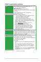
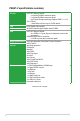
P8H67-V specifications summary CPU Chipset Memory Graphics Multi-GPU support Expansion slots GA1155 socket for Intel® Second Generation Core™ i7 / Core™ i5 / Core™ i3 Processors Supports 32nm CPU Supports Intel® Turbo Boost Technology 2.0 * The Intel® Turbo Boost Technology 2.0 support depends on the CPU types. ** Refer to www.asus.com for Intel® CPU support list.
P8H67-V specifications summary Storage LAN Audio USB ASUS special feature ASUS unique features Rear panel ports Intel® H67 Express Chipset: - 4 x Serial ATA 3Gb/s connectors (blue) - 2 x Serial ATA 6Gb/s connectors (gray) - Intel® Rapid Storage technology supports RAID 0, 1, 5, 10 VIA® VT6415: - 1 Ultra DMA 133/100 for up to 2 PATA devices PCIE Gigabit LAN controller ALC887 8-channel High Definition Audio CODEC Intel® H67 Express Chipset: - 12 x USB 2.0/1.
Internal connectors BIOS features Manageability Accessories Support DVD Form factor 4 x USB 2.0/1.1 connectors support additional 8 USB 2.0/1.1 ports 1 x IDE connector 1 x System panel connector 1 x S/PDIF Out connector 2 x SATA 6.0Gb/s connectors (gray) 4 x SATA 3.
xii
Chapter 1 Product introduction 1.1 Welcome! Thank you for buying an ASUS® P8H67-V motherboard! The motherboard delivers a host of new features and latest technologies, making it another standout in the long line of ASUS quality motherboards! Before you start installing the motherboard, and hardware devices on it, check the items in your package with the list below. 1.2 Package contents Check your motherboard package for the following items.
Intel® H67 Express Chipset The Intel® H67 Express Chipset is the latest single-chipset design to support the new 1155 socket Intel® Core™ i7 / Core™ i5 / Core™ i3 2nd generation processors. It provides improved performance by utilizing serial point-to-point links, allowing increased bandwidth and stability. Additionally, the H67 provides 2 SATA 6.0 Gb/s and 4 SATA 3.0 Gb/s ports for faster data retrieval at double the bandwidth of current bus systems.
Gigabit LAN solution The onboard LAN controller is a highly integrated Gb LAN controller. It is enhanced with an ACPI management function to provide efficient power management for advanced operating systems. 100% All High-quality Conductive Polymer Capacitors This motherboard uses all high-quality conductive polymer capacitors for durability, improved lifespan, and enhanced thermal capacity.
GPU Boost GPU Boost overclocks the integrated GPU in real time for the best graphics performance. User-friendly UI facilitates flexible frequency and voltage adjustments. Its ability to deliver multiple overclocking profiles also provides rapid and stable system-level upgrades. Fan Xpert ASUS Fan Xpert intelligently allows you to adjust the CPU and chassis fan speeds according to different ambient temperatures caused by different climate conditions in different geographic regions and your PC’s loading.
C.P.R. (CPU Parameter Recall) The BIOS C.P.R. feature automatically restores the CPU default settings when the system hangs due to overclocking failure. C.P.R. eliminates the need to open the system chassis and clear the RTC data. Simply shut down and reboot the system, and the BIOS automatically restores the CPU parameters to their default settings.
1.5 Motherboard overview Before you install the motherboard, study the configuration of your chassis to ensure that the motherboard fits into it. Ensure that you unplug the power cord before installing or removing the motherboard. Failure to do so can cause you physical injury and damage motherboard components. 1.5.1 Placement direction 1.5.2 Screw holes When installing the motherboard, ensure that you place it into the chassis in the correct orientation.
1.5.3 Motherboard layout 1 2 1 3 1 4 5 22.9cm(9.0in) KB_USB34 GPU Boost CPU_FAN SPDIFO _HDMI 6 DRAM_LED 8 2 CHA_FAN1 PWR_FAN PRI_IDE AAFP PCIEX1_1 VT6415 Lithium Cell CMOS Power EATXPWR P8H67-V AUDIO 7 MemOK! 30.5cm(12.
1.6 Central Processing Unit (CPU) The motherboard comes with a surface mount LGA1155 socket designed for the Intel® Second Generation Core™ i7 / Core™ i5 / Core™ i3 processors. Unplug all power cables before installing the CPU. • Upon purchase of the motherboard, ensure that the PnP cap is on the socket and the socket contacts are not bent. Contact your retailer immediately if the PnP cap is missing, or if you see any damage to the PnP cap/socket contacts/motherboard components.
3. Lift the load lever in the direction of the arrow until the load plate is completely lifted. Load plate 4. Remove the PnP cap from the CPU socket by lifting the tab only. PnP cap 5. Position the CPU over the socket, ensuring that the gold triangle is on the bottom‑left corner of the socket, and then fit the socket alignment keys into the CPU notches. The CPU fits in only one correct orientation.
6. Apply some Thermal Interface Material to the exposed area of the CPU that the heatsink will be in contact with, ensuring that it is spread in an even thin layer. Some heatsinks come with preapplied thermal paste. If so, skip this step. The Thermal Interface Material is toxic and inedible. DO NOT eat it. If it gets into your eyes or touches your skin, wash it off immediately, and seek professional medical help. 7.
1.6.2 Installing the CPU heatsink and fan The Intel® LGA1155 processor requires a specially designed heatsink and fan assembly to ensure optimum thermal condition and performance. • When you buy a boxed Intel® processor, the package includes the CPU fan and heatsink assembly. If you buy a CPU separately, ensure that you use only Intel®‑certified multi‑directional heatsink and fan. • Your Intel® LGA1155 heatsink and fan assembly comes in a push-pin design and requires no tool to install.
3. Connect the CPU fan cable to the connector on the motherboard labeled CPU_FAN. CPU FAN PWM CPU FAN IN CPU FAN PWR GND CPU_FAN P8H67-V P8H67-V CPU fan connector Do not forget to connect the CPU fan connector! Hardware monitoring errors can occur if you fail to plug this connector. 1.6.3 Uninstalling the CPU heatsink and fan To uninstall the CPU heatsink and fan: 1. Disconnect the CPU fan cable from the connector on the motherboard. 2. Rotate each fastener counterclockwise. 3.
4. Carefully remove the heatsink and fan assembly from the motherboard. 5. Rotate each fastener clockwise to ensure correct orientation when reinstalling. 1.7 System memory 1.7.1 Overview DIMM_B1 DIMM_B2 DIMM_A1 DIMM_A2 The motherboard comes with four Double Data Rate 3 (DDR3) Dual Inline Memory Modules (DIMM) sockets. A DDR3 module has the same physical dimensions as a DDR2 DIMM but is notched differently to prevent installation on a DDR2 DIMM socket.
1.7.2 Memory configurations You may install 512MB, 1GB, 2GB, and 4GB unbuffered non‑ECC DDR3 DIMMs into the DIMM sockets. • You may install varying memory sizes in Channel A and Channel B. The system maps the total size of the lower-sized channel for the dual-channel configuration. Any excess memory from the higher-sized channel is then mapped for single-channel operation. • According to Intel CPU specification, DIMM voltage below 1.65V is recommended to protect the CPU.
P8H67-V Motherboard Qualified Vendors List (QVL) DDR3-1333MHz capability Size SS/ DS Chip Brand 1GB SS A-Data Vendors Part No. A-Data AD31333001GOU A-Data AD31333G001GOU A-Data AD31333002GOU 2GB DS A-Data A-Data AD31333G002GMU 2GB DS - Apacer 78.A1GC6.9L1 2GB DS Apacer 78.A1GC6.
DDR3-1333MHz capability 1-16 SS/ DS Chip Brand 2GB SS MICRON 2GB DS Micron 4GB DS MICRON OCZ3F13334GK 4GB(2x2GB) DS OCZ OCZ3G1333LV4GK 4GB(2x2GB) OCZ OCZ3P1333LV4GK OCZ OCZ3X13334GK(XMP) OCZ Vendors Part No. Size MICRON MT8JTF25664AZ-1G4D1 Micron MT16JTF25664AZ-1G4F1 MICRON MT16JTF51264AZ-1G4D1 OCZ Chip No. Timing Voltage DIMM support D9LGK - - A* B* C* • • • 9KF27D9KPT 9 - • • • D9LGK - - • • • - - 9-9-9-20 1.7V • • • DS - - 9-9-9-20 1.
DDR3-1066MHz capability Vendors Part No. Size SS/DS Chip Brand Crucial Crucial CT12864BA1067.8FF CT25664BA1067.
1.7.3 Installing a DIMM Unplug the power supply before adding or removing DIMMs or other system components. Failure to do so can cause severe damage to both the motherboard and the components. 2 1. Press the retaining clips outward to unlock a DIMM socket. 2. Align a DIMM on the socket such that the notch on the DIMM matches the DIMM slot key on the socket. DIMM notch 1 1 DIMM slot key Unlocked retaining clip A DIMM is keyed with a notch so that it fits in only one direction.
1.8 Expansion slots In the future, you may need to install expansion cards. The following sub‑sections describe the slots and the expansion cards that they support. Unplug the power cord before adding or removing expansion cards. Failure to do so may cause you physical injury and damage motherboard components. 1.8.1 Installing an expansion card To install an expansion card: 1.
VGA configuration PCI Express operating mode PCIe x16_1 PCIe x16_2 Single VGA/PCIe card x16 (Recommended for single VGA card) N/A Dual VGA/PCIe card x16 x4 • In single VGA card mode, use the PCIe 2.0 x16_1 slot (blue) for a PCI Express x16 graphics card to get better performance. • PCIe x1 slot shares the bandwidth with PCIe x16_2 slot.
1.9 1. Jumpers Clear RTC RAM (3-pin CLRTC) This jumper allows you to clear the Real Time Clock (RTC) RAM in CMOS. You can clear the CMOS memory of date, time, and system setup parameters by erasing the CMOS RTC RAM data. The onboard button cell battery powers the RAM data in CMOS, which include system setup information such as system passwords. P8H67-V CLRTC 1 2 2 3 Normal (Default) Clear RTC P8H67-V Clear RTC RAM To erase the RTC RAM: 1. Turn OFF the computer and unplug the power cord. 2.
1.10 Connectors 1.10.1 Rear panel connectors 1 2 3 15 14 13 4 12 11 5 6 7 8 10 9 1. PS/2 Keyboard/Mouse COMBO port. This port is for a PS/2 keyboard/mouse. 2. Optical S/PDIF Out port. This port connects an external audio output device via an optical S/PDIF cable. 3. Video Graphics Adapter (VGA) port. This 15-pin port is for a VGA monitor or other VGA-compatible devices. 4. LAN (RJ-45) port. This port allows Gigabit connection to a Local Area Network (LAN) through a network hub.
Audio 2, 4, 6, and 8-channel configuration Port Headset 2-channel 4-channel 6-channel Light Blue Line In Line in Line in 8-channel Line in Lime Line Out Front Speaker Out Front Speaker Out Front Speaker Out Pink Mic In Mic In Mic in Mic in Orange - - Center/Subwoofer Center/Subwoofer Black - Rear Speaker Out Rear Speaker Out Rear Speaker Out Gray - - - Side Speaker Out 11. USB 2.0 ports 1 and 2. These two 4-pin Universal Serial Bus (USB) ports connect to USB 2.0/1.
1.10.2 1. Internal connectors Front panel audio connector (10-1 pin AAFP) This connector is for a chassis-mounted front panel audio I/O module that supports either High Definition Audio or AC`97 audio standard. Connect one end of the front panel audio I/O module cable to this connector.
3. CPU, Chassis, and Power fan connectors (4-pin CPU_FAN, 3-pin PWR_FAN, 4-pin CHA_FAN1 and CHA_FAN2) Connect the fan cables to the fan connectors on the motherboard, making sure that the black wire of each cable matches the ground pin of the connector. DO NOT forget to connect the fan cables to the fan connectors. Insufficient air flow inside the system may damage the motherboard components. They are not jumpers! DO NOT place jumper caps on the fan connectors.
4. Serial ATA connectors (7-pin SATA3G1-4, 7-pin SATA6G1-2) These connectors are for the Serial ATA signal cables for Serial ATA 3Gb/s or 6Gb/s hard disk and optical disk drives.
5. ATX power connectors (24-pin EATXPWR, 8-pin ATX12V) These connectors are for an ATX power supply. The plugs from the power supply are designed to fit these connectors in only one orientation. Find the proper orientation and push down firmly until the connectors completely fit.
6. USB connectors (10-1 pin USB56, USB78, USB910, USB1112) These connectors are for USB 2.0 ports. Connect the USB module cable to any of these connectors, then install the module to a slot opening at the back of the system chassis. These USB connectors comply with the USB 2.0 specification that supports up to 480Mbps connection speed.
8. IDE connector (40-1 pin PRI_EIDE) The onboard IDE connector is for Ultra DMA 133/100 signal cable. There are three connectors on each Ultra DMA 133/100 signal cable: blue, black, and gray.
9. System panel connector (20-8 pin PANEL) This connector supports several chassis-mounted functions. SPEAKER +5V Ground Ground Speaker PLED- PLED+ PLED PANEL IDE_LED PWRSW Reset Ground PWR Ground PIN 1 IDE_LED+ IDE_LED- P8H67-V RESET * Requires an ATX power supply P8H67-V System panel connector • System power LED (2-pin PLED) • This 2-pin connector is for the system power LED. Connect the chassis power LED cable to this connector.
1.11 Onboard switches Onboard switches allow you to fine-tune performance when working on a bare or open-case system. This is ideal for overclockers and gamers who continually change settings to enhance system performance. 1. MemOK! switch Installing DIMMs that are incompatible with the motherboard may cause system boot failure, and the DRAM_LED near the MemOK! switch lights continuously.
2. GPU Boost switch This switch allows you to enable or disable the GPU Boost function.
1.12 1. Onboard LEDs Standby Power LED The motherboard comes with a standby power LED that lights up to indicate that the system is ON, in sleep mode, or in soft-off mode. This is a reminder that you should shut down the system and unplug the power cable before removing or plugging in any motherboard component. The illustration below shows the location of the onboard LED. P8H67-V SB_PWR ON Standby Power OFF Powered Off P8H67-V Onboard LED 2.
1.13 Software support 1.13.1 Installing an operating system This motherboard supports Windows® XP / Vista / 7 Operating Systems (OS). Always install the latest OS version and corresponding updates to maximize the features of your hardware. • Motherboard settings and hardware options vary. Refer to your OS documentation for detailed information.
Chapter 2 BIOS information 2.1 Managing and updating your BIOS Save a copy of the original motherboard BIOS file to a USB flash disk in case you need to restore the BIOS in the future. Copy the original motherboard BIOS using the ASUS Update utility. 2.1.1 ASUS Update utility The ASUS Update is a utility that allows you to manage, save, and update the motherboard BIOS in Windows® environment. • ASUS Update requires an Internet connection either through a network or an Internet Service Provider (ISP).
The ASUS Update utility is capable of updating itself through the Internet. Always update the utility to avail all its features. Updating from a BIOS file 3. a. Select Update BIOS from file, then click Next. b. Locate the BIOS file from the Open window, then click Open. Follow the onscreen instructions to complete the updating process. 2.1.2 ASUS EZ Flash 2 The ASUS EZ Flash 2 feature allows you to update the BIOS without using an OS‑based utility.
3. Press to switch to the Drive field. 4. Press the Up/Down arrow keys to find the USB flash disk that contains the latest BIOS, and then press . 5. Press to switch to the Folder Info field. 6. Press the Up/Down arrow keys to find the BIOS file, and then press to perform the BIOS update process. Reboot the system when the update process is done. • This function supports USB flash disks with FAT 32/16 format and single partition only.
2.1.4 ASUS BIOS Updater The ASUS BIOS Updater allows you to update BIOS in DOS environment. This utility also allows you to copy the current BIOS file that you can use as a backup when the BIOS fails or gets corrupted during the updating process. The succeeding utility screens are for reference only. The actual utility screen displays may not be same as shown. Before updating BIOS 1. Prepare the motherboard support DVD and a USB flash drive in FAT32/16 format and single partition. 2.
Backing up the current BIOS To backup the current BIOS file using the BIOS Updater Ensure that the USB flash drive is not write-protected and has at least 1024KB free space to save the file. 1. At the FreeDOS prompt, type bupdater /o[filename] and press . D:\>bupdater /oOLDBIOS1.rom Filename Extension The [filename] is any user-assigned filename with no more than eight alphanumeric characters for the filename and three alphanumeric characters for the extension. 2.
Updating the BIOS file To update the BIOS file using BIOS Updater 1. At the FreeDOS prompt, type bupdater /pc /g and press . D:\>bupdater /pc /g 2. The BIOS Updater screen appears as below. ASUSTek BIOS Updater for DOS V1.07 Current ROM BOARD: P8H67-V VER: 0217 DATE: 09/25/2010 Update ROM BOARD: Unknown VER: Unknown DATE: Unknown PATH: A:\ P8H67V.ROM A: 4194304 2010-09-20 17:30:48 Note [Enter] Select or Load [Up/Down/Home/End] Move 3.
2.2 BIOS setup program Use the BIOS Setup program to update the BIOS or configure its parameters. The BIOS screens include navigation keys and brief online help to guide you in using the BIOS Setup program. Entering BIOS Setup at startup To enter BIOS Setup at startup: • Press during the Power-On Self Test (POST). If you do not press , POST continues with its routines. Entering BIOS Setup after POST To enter BIOS Setup after POST: • Press ++ simultaneously.
BIOS menu screen The BIOS setup program can be used under two modes: EZ Mode and Advanced Mode. You can change modes from the Exit menu or from the Exit/Advanced Mode button in the EZ Mode/Advanced Mode screen. EZ Mode By default, the EZ Mode screen appears when you enter the BIOS setup program. The EZ Mode provides you an overview of the basic system information, and allows you to select the display language, system performance mode and boot device priority.
Advanced Mode The Advanced Mode provides advanced options for experienced end-users to configure the BIOS settings. The figure below shows an example of the Advanced Mode. Refer to the following sections for the detailed configurations. To access the EZ Mode, click Exit, then select ASUS EZ Mode.
Menu items The highlighted item on the menu bar displays the specific items for that menu. For example, selecting Main shows the Main menu items. The other items (Ai Tweaker, Advanced, Monitor, Boot, Tool, and Exit) on the menu bar have their respective menu items. Back button This button appears when entering a submenu. Press or use the USB mouse to click this button to return to the previous menu screen.
2.3 Main menu The Main menu screen appears when you enter the Advanced Mode of the BIOS Setup program. The Main menu provides you an overview of the basic system information, and allows you to set the system date, time, language, and security settings. EFI BIOS Utility - Advanced Mode Main Ai Tweaker Exit Advanced Monitor BIOS Information BIOS Version Build Date ME Version 0217 x64 09/25/2010 7.0.0.1095 CPU Information Genuine Intel(R) CPU 0 @ 3.
Administrator Password If you have set an administrator password, we recommend that you enter the administrator password for accessing the system. Otherwise, you might be able to see or change only selected fields in the BIOS setup program. To set an administrator password: 1. Select the Administrator Password item and press . 2. From the Create New Password box, key in a password, then press . 3. Confirm the password when prompted. To change an administrator password: 1.
2.4 Ai Tweaker menu The Ai Tweaker menu items allow you to configure overclocking-related items. Be cautious when changing the settings of the Ai Tweaker menu items. Incorrect field values can cause the system to malfunction. The configuration options for this section vary depending on the CPU and DIMM model you installed on the motherboard. EFI BIOS Utility - Advanced Mode Ai Tweaker Main Exit Advanced Monitor Ai Overclock Tuner Auto Memory Frequency Boot Tool [X.M.P.
2.4.2 Memory Frequency [Auto] Allows you to set the memory operating frequency. Configuration options: [DDR3-800MHz] [DDR3-1066MHz] [DDR3-1333MHz] Selecting a very high memory frequency may cause the system to become unstable! If this happens, revert to the default setting. 2.4.3 EPU Power Saving MODE [Disabled] 2.4.4 GPU Boost 2.4.5 DRAM Timing Control Allows you to enable or disable the EPU power saving function.
The following three items appear only when you set both the Enhanced Intel SpeedStep Technology and Turbo Mode items to [Enabled]. Long duration power limit [Auto] Use <+>/<-> to adjust the value. Long duration maintained [Auto] Use <+>/<-> to adjust the value. Short duration power limit [Auto] Use <+>/<-> to adjust the value. Power Limit Control [Disabled] Allows you to enable or disable the power limit control function.
2.4.8 DRAM Voltage [Auto] Allows you to set the DRAM voltage. The values range from 1.185V to 2.135V with a 0.005V interval. According to Intel CPU specification, DIMMs with voltage requirement over 1.65V may damage the CPU permanently. We recommend you install the DIMMs with the voltage requirement below 1.65V. 2.4.9 VCCIO Voltage [Auto] 2.4.10 CPU PLL Voltage [Auto] 2.4.11 PCH Voltage [Auto] Allows you to set the VCCIO voltage. The values range from 0.7350V to 1.6850V with a 0.005V interval.
2.5 Advanced menu The Advanced menu items allow you to change the settings for the CPU and other system devices. Be cautious when changing the settings of the Advanced menu items. Incorrect field values can cause the system to malfunction.
Hyper-threading [Enabled] The Intel Hyper-Threading Technology allows a hyper-threading processor to appear as two logical processors to the operating system, allowing the operating system to schedule two threads or processes simultaneously. [Enabled] Two threads per activated core are enabled. [Disabled] Only one thread per activated core is enabled. Active Processor Cores [All] Allows you to choose the number of CPU cores to activate in each processor package.
CPU C3 Report [Disabled] Allows you to disable or enable the CPU C3 report to OS. Configuration options: [Disabled] [ACPI C-2] [ACPI C-3] CPU C6 Report [Enabled] Allows you to disable or enable the CPU C6 report to OS. Configuration options: [Enabled] [Disabled] Package C State limit [No Limit] We recommend that you set this item to [No Limit] for BIOS to automatically detect the C-State mode supported by your CPU. Configuration options: [No Limit] [C0] [C1] [C6] [C7] 2.5.
2.5.4 SATA Configuration While entering Setup, the BIOS automatically detects the presence of SATA devices. The SATA Port items show Not Present if no SATA device is installed to the corresponding SATA port. SATA Mode [IDE Mode] Allows you to set the SATA configuration. [Disabled] Disables the SATA function. [IDE Mode] Set to [IDE Mode] when you want to use the Serial ATA hard disk drives as Parallel ATA physical storage devices.
2.5.5 USB Configuration The items in this menu allow you to change the USB-related features. The USB Devices item shows the auto-detected values. If no USB device is detected, the item shows None. Legacy USB Support [Enabled] [Enabled] [Disabled] [Auto] Enables the support for USB 3.0 devices on legacy operating systems (OS). The USB devices can be used only for the BIOS setup program. Allows the system to detect the presence of USB devices at startup.
VIA Storage OPROM [Enabled] This item appears only when the VIA Storage Controller item is set to [Enalbed] and allows you to enable or disable the OptionROM of the VIA Storage controller. Configuration options: [Enabled] [Disabled] PCI Express x16_2 slot (black) bandwidth [Auto] [Auto] [X4 Mode] [x2 mode] The PCIe X16_2 slot runs at x4/x2 mode for system resource optimization. The PCIe X16_2 slot runs at x4 mode for high performance support. (PCIe X1_1, and PCIe X1_2 slots will be disabled.
2.5.7 APM Restore AC Power Loss [Power Off] [Power On] [Power Off] [Last State] The system goes into on state after an AC power loss. The system goes into off state after an AC power loss. The system goes into either off or on state, whatever the system state was before the AC power loss. Power On By PS/2 Keyboard [Disabled] [Disabled] [Space Bar] [Ctrl-Esc] [Power Key] Disables the Power On by a PS/2 keyboard. Sets the Space Bar on the PS/2 keyboard to turn on the system.
2.6 Monitor menu The Monitor menu displays the system temperature/power status, and allows you to change the fan settings.
2.6.3 [Disabled] [Enabled] CPU Q-Fan Control [Enabled] Disables the CPU Q-Fan control feature. Enables the CPU Q-Fan control feature. CPU Fan Speed Low Limit [600 RPM] This item appears only when you enable the CPU Q-Fan Control feature and allows you to disable or set the CPU fan warning speed.
Chassis Fan Profile [Standard] This item appears only when you enable the Chassis Q-Fan Control feature and allows you to set the appropriate performance level of the chassis fan. [Standard] Sets to [Standard] to make the chassis fan automatically adjust depending on the chassis temperature. [Silent] Sets to [Silent] to minimize the fan speed for quiet chassis fan operation. [Turbo] Sets to [Turbo] to achieve maximum chassis fan speed.
2.7 Boot menu The Boot menu items allow you to change the system boot options.
2.7.3 [Force BIOS] Option ROM Messages [Force BIOS] [Keep Current] The third-party ROM messages will be forced to display during the boot sequence. The third-party ROM messages will be displayed only if the third-party manufacturer had set the add-on device to do so. 2.7.4 Setup Mode [EZ Mode] 2.7.5 Boot Option Priorities [Advanced Mode] Sets Advanced Mode as the default screen for entering the BIOS setup program. [EZ Mode] Sets EZ Mode as the default screen for entering the BIOS setup program.
2.8 Tools menu The Tools menu items allow you to configure options for special functions. Select an item then press to display the submenu. EFI BIOS Utility - Advanced Mode Ai Tweaker Main Advanced Exit Monitor Boot Tool Be used to update BIOS > ASUS EZ Flash Utility > ASUS O.C. Profile 2.8.1 ASUS EZ Flash 2 Allows you to run ASUS EZ Flash 2. When you press , a confirmation message appears.
2.9 Exit menu The Exit menu items allow you to load the optimal default values for the BIOS items, and save or discard your changes to the BIOS items. You can access the EZ Mode from the Exit menu. Exit Load Optimized Defaults Save Changes & Reset Discard Changes & Exit ASUS EZ Mode Launch EFI Shell from filesystem device Load Optimized Defaults This option allows you to load the default values for each of the parameters on the Setup menus.
ASUS contact information ASUSTeK COMPUTER INC. Address Telephone Fax E-mail Web site Technical Support Telephone Online support 15 Li-Te Road, Peitou, Taipei, Taiwan 11259 +886-2-2894-3447 +886-2-2890-7798 info@asus.com.tw www.asus.com.tw +86-21-38429911 support.asus.
(510)739-3777/(510)608-4555 800 Corporate Way, Fremont, CA 94539. Asus Computer International Signature : Date : Representative Person’s Name : Oct. 31, 2010 Steve Chang / President This device complies with part 15 of the FCC Rules. Operation is subject to the following two conditions: (1) This device may not cause harmful interference, and (2) this device must accept any interference received, including interference that may cause undesired operation.