E2949 ® User Guide
E2949 Third Edition V3 December 2006 Copyright © 2006 ASUSTeK COMPUTER INC. All Rights Reserved. No part of this manual, including the products and software described in it, may be reproduced, transmitted, transcribed, stored in a retrieval system, or translated into any language in any form or by any means, except documentation kept by the purchaser for backup purposes, without the express written permission of ASUSTeK COMPUTER INC. (“ASUS”).
Contents Features About this guide.......................................................................................... iv WiFi-AP Solo specifications summary....................................................... v Chapter 1: Product introduction 1.1 Welcome!....................................................................................... 1-2 1.3 LED and antenna port................................................................... 1-4 1.2 1.4 Features....................................
About this guide This user guide contains the information you need to install and configure your ASUS WiFi-AP Solo wireless solution. How this guide is organized This guide contains the following parts: • Chapter 1: Product introduction This chapter describes the general features of the ASUS WiFi-AP Solo wireless solution. The chapter also presents the LED indications, and recommended WiFi-AP Solo network settings.
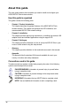
WiFi-AP Solo specifications summary Standard IEEE 802.11b/g Data rate 802.11g: 6, 9, 12, 18, 24, 36, 48, 54Mbps 802.11b: 1, 2, 5.5, 11Mbps Security Access Point mode: WEP WPA WPA2 Network architechture types Access point mode Station mode: Infrastructure mode and Ad-Hoc mode Frequency band 2.4~2.5GHz Operating range 802.11g Indoor: 80ft (30m) Outdoor: 200ft (60m) LOS* 802.
vi
Chapter 1 This chapter describes the general features of the ASUS WiFi-AP Solo wireless solution. The chapter also presents the LED indications, and recommended WiFi-AP Solo network settings.
1.1 Welcome! Thank you for choosing the ASUS WiFi-AP Solo wireless solution! The WiFi-AP Solo is an easy-to-use wireless local area network (WLAN) adapter designed for home or office use. The WiFi-AP Solo is backward compatible with the earlier IEEE 802.11b standard allowing seamless integration of both wireless LAN standards in a single network. The WiFi-AP Solo also supports several wireless network configuration including Infrastructure, Ad-hoc, and Access Point.
54Mbps speed advantage With data transmission rate up to five times faster than IEEE 802.11b standards, the WiFi-AP Solo breaks the wireless data transmission speed barrier to give you faster Internet connection and file sharing capabilities. Easy integration The WiFi-AP Solo is compatible with all IEEE 802.11b devices so you can still use your IEEE 802.11b devices in the WiFi-AP Solo network.
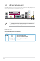
1.3 LED and antenna port The WiFi-AP Solo comes with a green data transmission LED (AIR) and an antenna port located at the motherboard rear panel. Antenna port AIR LED • • The location of the WiFi-AP Solo data transmission LED and antenna port may vary on motherboard models. The back I/O may vary depending on the models. LED indicators Refer to the table below for LED indications. LED Air LED 1-4 Status On Off Blinking quickly Blinking slowly Indication Power on but no data activity.
1.4 Choosing an appropriate wireless network You can use the ASUS WiFi-AP Solo in various wireless network configurations. It is recommended that you select the most appropriate configuration for your home or office network before setting up the WiFi‑AP Solo. The following pictures and descriptions are for reference only and may not exactly match your actual network configuration.
1.4.1 Access Point Mode (AP Mode) If you wish to share the Internet access with the wireless stations in your environment, you can configure the WiFi-AP Solo in an access point mode (AP Mode). In this mode, the WiFi-AP Solo becomes the wireless access point that provides local area network and Internet access for your wireless stations. The requirement of using AP Mode function is an onboard Ethernet LAN adapter with the driver properly installed.
1.4.2 Station mode The station mode is centered on a wireless access point (AP) that provides Internet access and LAN communication for the wireless stations. In station mode, the wireless LAN stations communicate with each other via the wireless AP. In this mode, your WiFi-AP Solo acts as a wireless adapter. It communicates with the LAN computers and accesses Internet through the wireless AP.
1-8
Chapter 2 This chapter provides step by step instructions on installing the WiFi-AP Solo drivers and utilities to your computer. This part also provides information on installing the antenna.
2.1 Installation 2.1.1 System requirements Before installing the WiFi-AP Solo drivers and utilities, make sure that your system meets the following requirements. • ASUS motherboard with WiFi-AP Solo onboard solution • Intel® Pentium™ 4 • Minimum 128MB system memory • Operating system: Windows® XP/ XP-64bit/ Server 2003/ Server 2003 64-bit • Optical drive for utilities and driver installation 2.1.
2.1.3 Signal range The signal range of WiFi-AP Solo depends on the operating environment. Obstacles such as walls and metal barriers could reflect or absorb radio signals. Devices such as microwave stove can also greatly interfere with the wireless network. Signal range: 802.11g: Indoor 80ft (30m), outdoor (LOS, Light-Of-Sight) 200ft (60m) 802.
2.2 Driver and utilities installation • The contents of the motherboard support CD are subject to change without notice. Visit the ASUS website for driver/utilities updates. • If you use a Windows® operating system, your computer auto‑detects the WiFi-AP Solo when system boots and displays an Add New Hardware Wizard window. Click Cancel then proceed with the following instructions. To install the WiFi-AP Solo driver and utilities: 1. 2. 3. Place the motherboard support CD to the optical drive.
Chapter 3 This chapter provides information on how to set up the WiFi-AP Solo in your home or office network.
3.1 About the setup utilities After you have installed the WiFi-AP Solo drivers and utilities to your system, you are now ready to setup the WiFi-AP Solo in your network. Make sure that you have selected the most appropriate configuration for your wireless network before you proceed. Refer to section 1.4 for details. Make sure you have connected the supplied antenna to the antenna connector on the motherboard, or the WiFi-AP Solo may not be able to detect other wireless devices in your environment.
3.2 Setting up with WiFi-AP Solo Wizard You can create your own wireless local area network (WLAN) in your home using the WiFi-AP Solo Access Point Mode (AP Mode) feature. Create your own WLAN if: 1. 2. your computer is connected to the Internet; and the operating system of your computer is Windows® XP/ XP 64-bit/ Server 2003/ Server 2003 64-bit. Install the WiFi-AP Solo software from the support CD.
3.2.1 1. To launch the WiFi-AP Solo setup wizard, right-click the system tray icon and select WiFi-AP Solo Wizard. 2. Select Access Point and click Next. 3. The system automatically generates an SSID for the AP mode. You can rename the SSID, if desired. 4. 3-4 Setting up the AP Mode Select a Network Security level for your AP mode. The configurable options are None, Share-WEP, WPAPSK, and WPA2-PSK. Refer to section 3.4 for detailed security information. Select an appropriate level and click Next.
5. If you select Share-WEP, WPAPSK, or WPA2-PSK in Step 4, you are required to input a password. You can choose to configure the password in either ASCII or HEX mode. If you choose HEX mode, input 10 hex digits for 64-bit encrytion, or 26 hex digits for 128-bit encryption. Click Next to continue. 6. Select your Internet connection and click Next. 7. The AP mode configuration is complete. Record the setup information on your note and click Finish to quit the ASUS WiFi-AP Solo wizard.
3.2.2 Setting up the station mode In the Infrastructure mode, you can connect to the LAN or Internet, or both, through a wireless AP. 1. To launch the WiFi-AP Solo setup wizard, right-click the system tray icon and select ASUS WiFi-AP Solo Wizard. 2. Select Station and click Next. 3. Click Finish. 3. Double-click the wireless icon on the task bar to configure the Windows® Wireless Zero Configuration. Refer to Section 3.3.
3.3 Setting up via setup utility 3.3.1 How to launch Wifi-AP Solo utility You can launch Wifi-AP Solo either from the Windows® Program menu or the tray icon. The tray icon is an optional quick launch to be enabled by a user. Windows® Program Menu It is the absolute way to launch the WiFi-AP Solo from the program folder. We recommend that you uninstall the WiFi-AP Solo utility by clicking Start > Control Panel > Add or Remove Programs.
• • Radio Off When this item is checked, the radio is turned off to save power. When the radio is off, the links with other wireless network nodes are disconnected. Disable Adapter When this item is checked, the wireless LAN adapter is disabled to increase performance in terms of better system resource management and CPU utilization. If the wireless configuration is in AP mode, checking Radio Off will cause the sub-network belonging to the AP to disconnect with the Internet/intranet.
• Up Time Config page This page displays the basic information of the WiFi-AP Solo: Statistics page You could watch the Tx/Rx status of current wireless connection. It provides a statistic analysis of packet transition. Advanced page This page presents all the access points in the system. Internet Connection Sharing (ICS) page This page is enabled when the WiFi-AP Solo is switched to AP mode. This page allows you to configure your Internet connection which you wish to share.
3.3.3 Setting up AP Mode Open the setup utility by double-clicking the utility icon on the desktop. The setup utility contains six buttons - Status, Config, Survey, Statistics, Advanced and ICS in the left column. The Survey button is greyed out in AP mode and the ICS button is disabled when in the station mode. 3-10 1. Open the setup utility and click Config button. Click the AP/ Station Mode switch button - To Access Point Mode. The WiFiAP Solo is switched to AP mode in several seconds. 2.
4. You are directed to the Wireless Network Properties page to set up the AP mode. In this page, you can change the SSID, select the communication channel and specify the network security. When configuration is complete, click OK to apply the settings and return to the setup wizard. 5. The AP mode configuration is finished. You can view in the Association Table of the Config page all the wireless stations that have connected to the WiFi-AP Solo (AP mode).
3.3.4 Setting up the station mode Open the setup utility by double-clicking the utility icon on the desktop. A message pops up asking you to set up the station mode via the Windows® Wireless Zero Configuration (WZC) service. The actual screens of Windows® Wireless Zero Configuration service may differ according to the Operating System (OS) of your computer. To configure the Windows® Wireless Zero Configuration (WZC) service, follow the instruction below to make the settings. 1.
To set up the wireless connection properties, right-click the wireless icon on the task bar and select Open Network Connection. Then right-click the network connection icon and select Properties to open the Wireless Network Connection Status page. 1. The General page shows status, duration, speed, and signal strength. Signal strength is represented by green bars with 5 bars indicating excellent signal and 1 bar meaning poor signal. 2. Select “Wireless Networks” tab to show Preferred networks.
3. The Authentication page allows you to add security settings. Read Windows help for more information. 4. The Advanced page allows you to set firewall and sharing. Read Windows help for more information. In the station mode, the Windows® Zero Configuration does not support WPA2 PSK and cannot connect the access point with WPA2 PSK. Visit the Microsoft download center to download the WPA2 package.
3.4 Setting up wireless security To protect your wireless network, you need to setup a security mechanism on your WiFi-AP Solo. Under AP mode, only Open, Shared, and WPA-PSK are supported. Under Station mode, all the security modes listed below are supported. Network authentication Network authentication uses certain types of mechanism to identify authenticated wireless clients.
Encryption Encryption is used to convert plain text data into unreadable codes with certain type of algorithm before capsulation for wireless transmission. WiFi-AP Solo supports the following encryption methods: WEP: WEP stands for Wired Equivalent Privacy. It uses 64 or 128-bit static keys. You can let the system generate the WEP keys by inputting a Passphrase. TKIP: Temporal Key Integrity Protocol (TKIP) dynamically generates unique keys to encypt every data packet in a wireless session.
Glossary 4-1
Access Point (AP) A networking device that seamlessly connects wired and wireless networks. Access Points combined with a distributed system support the creation of multiple radio cells that enable roaming throughout a facility. Ad Hoc A wireless network composed solely of stations within mutual communication range of each other (no Access Point). Basic Rate Set This option allows you to specify the data transmission rate.
Each subchannel in the COFDM implementation is about 300 KHz wide. At the low end of the speed gradient, BPSK (binary phase shift keying) is used to encode 125 Kbps of data per channel, resulting in a 6,000-Kbps, or 6 Mbps, data rate. Using quadrature phase shift keying, you can double the amount of data encoded to 250 Kbps per channel, yielding a 12-Mbps data rate. And by using 16-level quadrature amplitude modulation encoding 4 bits per hertz, you can achieve a data rate of 24 Mbps. The 802.
Direct-sequence systems communicate by continuously transmitting a redundant pattern of bits called a chipping sequence. Each bit of transmitted data is mapped into chips and rearranged into a pseudorandom spreading code to form the chipping sequence. The chipping sequence is combined with a transmitted data stream to produce the output signal.
Ethernet The most widely used LAN access method, which is defined by the IEEE 802.3 standard. Ethernet is normally a shared media LAN meaning all devices on the network segment share total bandwidth. Ethernet networks operate at 10Mbps using CSMA/CD to run over 10-BaseT cables. Firewall A firewall determines which information passes in and out of a network. NAT can create a natural firewall by hiding a local network’s IP addresses from the Internet.
The 802.11b spectrum is plagued by saturation from wireless phones, microwave ovens and other emerging wireless technologies, such as Bluetooth. In contrast, 802.11a spectrum is relatively free of interference. The 802.11a standard gains some of its performance from the higher frequencies at which it operates. The laws of information theory tie frequency, radiated power and distance together in an inverse relationship. Thus, moving up to the 5-GHz spectrum from 2.
Infrastructure A wireless network centered about an access point. In this environment, the access point not only provides communication with the wired network but also mediates wireless network traffic in the immediate neighborhood. IP (Internet Protocol) The TCP/IP standard protocol that defines the IP datagram as the unit of information passed across an Internet and provides the basis for connectionless packet delivery service.
NIC (Network Interface Card) A network adapter inserted into a computer so that the computer can be connected to a network. It is responsible for converting data from stored in the computer to the form transmitted or received. Packet A basic message unit for communication across a network. A packet usually includes routing information, data, and sometimes error detection information. Pass Phrase The Wireless Settings utility uses an algorithm to generate four WEP keys based on the typed combination.
Station Any device containing IEEE 802.11 wireless medium access conformity. Subnet Mask A subnet mask is a set of four numbers configured like an IP address. It is used to create IP address numbers used only within a particular network. TCP (Transmission Control Protocol) The standard transport level protocol that provides the full duplex, stream service on which many application protocols depend. TCP allows a process or one machine to send a stream of data to a process on another.
4-10
Appendix The Appendix lists the wireless LAN channels available for use in your country or location, and safety warning statements A-1
Wireless LAN channels The IEEE 802.11b/g standard for wireless LAN allocated the 2.4 GHz frequency band into 13 overlapping operating channels. Each channel corresponds to a different set of frequencies. The table below shows the center frequencies of each channel. Channel Center Channel Frequency Center Frequency 1 2.412 GHz 8 2.447 GHz 2 2.417 GHz 9 2.452 GHz 3 2.422 GHz 10 2.457 GHz 4 2.427 GHz 11 2.462 GHz 5 2.432 GHz 12 2.467 GHz 6 2.437 GHz 13 2.472 GHz 7 2.
Country/Region (Regulating Body) Available Channels Hungary (RTT&E/EMC/LVD) Channels 1 to 13 Iceland (RTT&E/EMC/LVD) Channels 1 to 13 Ireland (RTT&E/EMC/LVD) Channels 1 to 13 Italy (RTT&E/EMC/LVD) Channels 1 to 13 Japan (TELEC) Channels 1 to 14 Luxembourg (RTT&E/EMC/LVD) Channels 1 to 13 Malaysia (SIRIM/CMC) Channels 1 to 13 Mexico Channels 9 to 11 Netherlands Antilles (RTT&E/EMC/LVD) Channels 1 to 13 Netherlands/Holland (RTT&E/EMC/LVD) Channels 1 to 13 New Zealand (PTC) Channels 1 to
Safety statements Federal Communications Commission Statement This device complies with FCC Rules Part 15. Operation is subject to the following two conditions: • This device may not cause harmful interference, and • This device must accept any interference received, including interference that may cause undesired operation. This equipment has been tested and found to comply with the limits for a class B digital device, pursuant to Part 15 of the Federal Communications Commission (FCC) rules.
Regulatory Information/Disclaimers Installation and use of this Wireless LAN device must be in strict accordance with the instructions included in the user documentation provided with the product. Any changes or modifications (including the antennas) made to this device that are not expressly approved by the manufacturer may void the user’s authority to operate the equipment.
Caution Statement of the FCC Radio Frequency Exposure This Wireless LAN radio device has been evaluated under FCC Bulletin OET 65C and found compliant to the requirements as set forth in CFR 47 Sections 2.1091 and 15.247(b)(5) addressing RF Exposure from radio frequency devices. The radiation output power of this Wireless LAN device is far below the FCC radio frequency exposure limits.