NOTEBOOK PC USER’S MANUAL Product Name: Notebook PC Manual Revision: 1.
SAFETY STATEMENTS Federal Communications Commission Statement This device complies with FCC Rules Part 15. Operation is subject to the following two conditions: • This device may not cause harmful interference, and • This device must accept any interference received, including interference that may cause undesired operation. This equipment has been tested and found to comply with the limits for a class B digital device, pursuant to Part 15 of the Federal Communications Commission (FCC) rules.
Nordic Cautions (for Notebook PC with Lithium-Ion Battery) CAUTION! Danger of explosion if battery is incorrectly replaced. Replace only with the same or equivalent type recommended by the manufacturer. Dispose of used batteries according to the manufacturer’s instructions. (English) VORSICHT! Explosionsgetahr bei unsachgemäßen Austausch der Batterie. Ersatz nur durch denselben oder einem vom Hersteller empfohlenem ähnlichen Typ. Entsorgung gebrauchter Batterien nach Angaben des Herstellers.
CTR 21 Approval (for Notebook PC with built-in Modem) Danish Dutch English Finnish French German Greek 4
Italian Portuguese Spanish Swedish 5
Contents SAFETY STATEMENTS 2 Federal Communications Commission Statement .............................................. 2 Canadian Department of Communications Statement ....................................... 2 Nordic Cautions (for Notebook PC with Lithium-Ion Battery) .............................. 3 Macrovision Corporation Product Notice ............................................................ 3 CTR 21 Approval (for Notebook PC with built-in Modem) ..................................
SECTION 4 USING THE NOTEBOOK PC 33 Floppy Disk Drive ................................................................................................... 34 CD/DVD-ROM Drive .............................................................................................. 35 Laser Safety ...................................................................................................... 35 CDRH Regulations ...........................................................................................
SECTION 5 CONFIGURING THE BIOS 57 Updating Your BIOS ............................................................................................... 58 Creating a BIOS Update Floppy Disk ............................................................... 58 Updating BIOS Procedures .............................................................................. 59 BIOS Setup Program ............................................................................................. 60 BIOS Menu Bar .....................
SECTION 1 INTRODUCING THE NOTEBOOK PC About This User’s Manual Caring Information Transportation Precautions 9
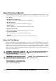
About This User’s Manual You are reading the Notebook PC User’s Manual. This User’s Manual provides information on the various components in the Notebook PC and how to use them. The following are major sections of this User’s Manuals: 1. Introducing the Notebook PC Introduces you to the Notebook PC and this User’s Manual. 2. Knowing the Parts Gives you information on the Notebook PC’s components. 3. Getting Started Gives you information on getting started with the Notebook PC. 4.
Caring Information WARNING! The following safety precautions will increase the life of the Notebook PC. Follow all precautions and instructions. Except as described in this manual, refer all servicing to qualified personnel. Do not use damaged power cords, accessories, or other peripherals. Do not use strong solvents such as thinners, benzene or other chemicals on or near the surface. Disconnect the AC power and remove the battery pack(s) before cleaning.
Transportation Precautions To prepare the Notebook PC for transport, you should turn it OFF and disconnect all external peripherals to prevent damage to the connectors. The hard disk drive’s head retracts when the power is turned OFF to prevent scratching of the hard disk surface during transport. Therefore, you should not transport the Notebook PC while the power is still ON. Close the display panel and check that it is latched securely in the closed position to protect the keyboard and display panel.
SECTION 2 KNOWING THE PARTS Top Side Front Side Left Side Right Side Rear Side 13
Top Side Refer to the diagram below to identify the components on the top side of the Notebook PC. Display Panel Microphone Cooling Fan and air entry ~ S1 ‘ ! @ # $ % ^ S2 & Sys Rq TV * ( ) Prt Sc _ + { Tab Back Space } [ ] \ Keyboard " Enter Touchpad Touchpad Buttons A 1 Status LEDs Very Light All-in-One: Including the battery pack weighs only 6.28lbs (2.85Kg). 14 2.
The following describes the components of the Notebook PC as viewed from the top as shown by the illustration on the previous page. Display Panel The display panel functions the same as a desktop monitor. The Notebook PC uses a 1024x768 14.1” active matrix TFT LCD, which provides excellent viewing like that of desktop monitors. Unlike desktop monitors, the LCD panel does not produce any radiation or flickering, so it is easier on the eyes.
Front Side Refer to the diagram below to identify the components on the front side of the Notebook PC. Power Indicator Display Panel Latch 35mm Display Panel Latch Stereo Speaker Charge Indicator Power Switch Stereo Speaker 310mm The following describes the front components of the Notebook PC as shown by the picture above. Stereo Speakers The two built-in speakers allow you to hear stereo audio without additional attachments.
Left Side Refer to the diagram below to identify the components on the left side of the Notebook PC. Air Vent Kensington® Lock Port Fast Infrared Port DC Power Input Jack PC Card (PCMCIA) Eject PC Card (PCMCIA) Sockets 256mm The following describes the components on the left side of the Notebook PC as shown by the illustration above. L Kensington® Lock Port The Kensington® lock port allows the Notebook PC to be secured using Kensington® compatible Notebook PC security products.
Right Side Refer to the diagram below to identify the components on the right side of the Notebook PC. CD/DVD Activity LED Floppy Disk Drive CD/DVD Emergency Eject CD/DVD Eject Floppy Eject Volume Control 256mm The following describes the components on the right side of the Notebook PC as shown by the illustration above. Floppy Disk Drive and Floppy Eject This is a standard 1.44MB floppy disk drive with Japanese 3-mode floppy support.
Volume Control The volume control wheel allows fast adjustment of the master audio output volume. For maximum volume, the digital volume controlled through Windows™ “Volume Control” on the taskbar must also be maximized. Hard Disk Drive The hard disk drive is fixed internally. There is no removable hard disk drive bay. 2.
Rear Side Refer to the diagram below to identify the components on the rear side of the Notebook PC. Docking Port Serial Port External Monitor Port PS/2 Port 35mm Audio In Headphone Mic In Parallel Port Modem/LAN Port TV Out Port 2 USB Ports 310mm The following describes the components on the rear side of the Notebook PC as shown by the illustration above. Headphone (Jack) The stereo headphone jack is used to connect the Notebook PC’s audio out signal to amplified speakers or headphones.
NOTE: The built-in modem and fast-Ethernet is also available by a dealer (not by user) upgrade if you did not choose them at the time of purchase. A modem and/or LAN can be user-installed as a PCMCIA card. WARNING! The built-in modem does not support the voltage used in digital phone systems. Do not connect the modem port to a digital phone system or else damage will occur to the Notebook PC.
2.
SECTION 3 GETTING STARTED Inserting/Removing Battery Pack Using the Battery Pack Operating Systems Power Connection Powering ON Your Notebook PC Save-to-Disk Partition Restarting or Rebooting LED Status Indicators Using the Keyboard 23
Inserting and Removing the Battery Pack Your Notebook PC may or may not have its battery pack inserted. If your Notebook PC does not have its battery pack inserted, there will be a large opening on the bottom of the Notebook PC. Use the following procedures to install or remove the battery pack. To insert the battery pack: To remove the battery pack: 1. Insert the battery pack with the connector side over the connectors in the battery compartment as indicated by arrow [1]. 1.
Using the Battery Pack Before using your Notebook PC on the road Before you use your Notebook PC on the road, you will have to charge the battery pack. The battery pack begins to charge as soon as the Notebook PC is connected to external power. Fully charge the battery pack before using it for the first time. A new battery pack must completely charge before the Notebook PC is disconnected from external power. The battery pack is fully charged when the battery charge light turns OFF.
Power Connection Your Notebook PC comes with a universal AC-DC adapter. That means that you may connect the power cord to any 110V-120V as well as 220V-240V outlets without setting switches or using power converters. Different countries may require that an adapter be used to connect the provided US-standard AC power cord to a different standard. Most hotels will provide universal outlets to support different power cords as well as voltages.
Powering ON Your Notebook PC The Notebook PC’s power-ON message will appear on the screen followed by a short beep when you turn it ON. If necessary, you may adjust the brightness by using the hot keys. If you need to run the BIOS Setup to set or modify the system configuration, press [F2] upon bootup to enter the BIOS Setup. WARNING! Never turn OFF or reset your Notebook PC while the hard disk or floppy disk is in use and the activity LED is lit; doing so can result in loss or destruction of your data.
Save-to-Disk Partition The Notebook PC supports Advanced Power Management to save battery power and extend its working time. One type of power management is “Save-to-Disk.” Save-to-Disk is a suspend mode where your operating system and application data is saved to a separate partition and retrieved when the Notebook PC comes out of suspend mode. A partition is a space on the hard disk drive equivalent to having a second hard disk drive.
LED Status Indicators There are several LED status indicators on the Notebook PC. The LED status indicators give information on the Notebook PC’s current operating and keyboard statuses. The following illustration shows the meaning of each status LED. A 1 Capital Number Lock Lock Charge Indicators Activity Power Indicator Indicators The following gives a description for each of the LED status indicators. A Capital Lock Indicates that capital lock [Caps Lock] is activated when lighted.
Using the Keyboard Colored Hot Keys The following defines the colored hot keys on the Notebook PC’s keyboard. The colored commands can only be accessed by first pressing and holding the function key while pressing a key with a colored command. Suspend: Places the Notebook PC in suspend mode (either Save-to-RAM or Save-toDisk depending on BIOS setup). This is not the same as “stand by” in MS Windows. F1 S1 S1: Programmable Key 1.
Microsoft Windows™ Keys There are two special Windows™ keys on the keyboard as described below. The key with the Windows™ Logo activates the Start menu located at the bottom left of the Windows™ desktop. The other key, which looks like a Windows™ menu with a small cursor, activates the properties menu and is equivalent to pressing the right mouse button on a Windows™object.
Keyboard as Cursors The keyboard can be used as cursors while Number Lock is ON or OFF in order to increase navigation ease while entering numeric data in spreadsheets or similar applications. With Number Lock OFF, press and one of the cursor keys shown below. For example <8> for up, for down, for left, and for right. With Number Lock ON, use and one of the cursor keys shown below.
SECTION 4 USING THE NOTEBOOK PC Floppy Disk Drive CD-ROM Drive DVD-ROM Drive Pointing Device PS/2 Connection External Monitor Connection PC Cards (PCMCIA) External Audio Connections IR Wireless Communication Universal Serial Bus AC Power System Battery Power System Power Management Modes System Memory Expansion Processor Upgrades Modem and Network Securing Your Notebook PC 33
This Section describes the basic features and procedures for using your Notebook PC. Topics covered include the floppy drive, CD/DVD-ROM drive, pointing device, and other input and output devices. Floppy Disk Drive The Notebook PC features a slim 3.5-inch floppy disk drive that accepts a standard 1.44MB (or 720KB) floppy diskette. The eject button is placed on the top edge of the floppy disk drive for easy access, unlike desktop PCs with the eject button on the bottom of the floppy disk drive.
CD/DVD-ROM Drive NOTE: The letters “CD-ROM” or “CD” will mainly be used in all documentation because of its wide familiarity, although “CD/DVD-ROM” or “CD/DVD” should be more appropriate with the DVD-ROM model Notebook PC. Please substitute where appropriate. The CD-ROM (Compact Disc Read Only Memory) drive can support all the popular formats: Audio/ Music CDs; Photo CDs; MS-DOS MSCDEX Mode 1 / Mode 2; CD-ROM/XA; CD-I; and Video CDs.
DVD-ROM Drive (optional) Overview The Notebook PC comes in a DVD-ROM drive or a CD-ROM drive model. For DVD support on your Notebook PC, you must select the DVD-ROM drive at the time of purchase instead of the standard CDROM. Future upgrades can be done by an authorized dealer. In order to view DVD titles, you must install the provided MPEG2 video decoder software and the DVD viewer software included on the DVD module driver support CD. The DVD-ROM drive allows the use of both CD and DVD discs.
Regional Playback Information Playback of DVD movie titles involves decoding MPEG2 video, digital AC3 audio and decryption of CSS protected content. CSS (sometimes called copy guard) is the name given to the content protection scheme adopted by the motion picture industry to satisfy a need to protect against unlawful content duplication. Although the design rules imposed on CSS licensors are many, one rule that is most relevant is playback restrictions on regionalized content.
Using the CD-ROM Drive CD-ROM discs and equipment must be handled with care because of the precise mechanics involved. Keep in mind the important safety instructions from your CD suppliers. Unlike desktop CD-ROM drives, the Notebook PC uses a hub to hold the CD in place regardless of the angle. When inserting a CD, it is important that the CD be pressed onto the center hub or else the CD-ROM drive tray will scratch the CD.
Using a CD A CD drive letter should be present regardless of the presence of a CD disc in the drive. After the CD is properly inserted, data can be accessed just like with hard disk drives; except that nothing can be written to or changed on the CD. Vibration is normal for all high-speed CD-ROM drives due to unbalance CDs or CD printings. To decrease vibration, do not place labels on the CD and use the Notebook PC on an even surface.
Pointing Device The Notebook PC’s integrated touchpad pointing device is fully compatible with all two/three-button and scrolling knob PS/2 mice. The touchpad is pressure sensitive and contains no moving parts; therefore, mechanical failures can be avoided. A device driver is still required for working with some application software. See the Driver & Utility Guide for information on drivers and utilities for the touchpad.
Double-clicking/Double-tapping - This is a common skill for launching a program directly from the corresponding icon you select. Move the cursor over the icon you wish to execute, press the left button or tap the pad twice in rapid succession, and the system launches the corresponding program. If the interval between the clicks or taps is too long, the operation will not be executed. You can set the double-click speed using the Windows Control Panel “Mouse.
Caring for the Touchpad The touchpad is a pressure sensitive device. If not properly cared for, it can be easily damaged. Take note of the following precautions. • • • • Make sure the touchpad does not come into contact with dirt, liquids or grease. Do not touch the touchpad if your fingers are dirty or wet. Do not rest heavy objects on the touchpad or the touchpad buttons. Do not scratch the touchpad with your finger nails or any hard objects. NOTE: The touchpad responds to movement not force.
External Display Connections (optional) Monitor Out Example As you can see here, connecting an external monitor is just like on desktop PC. Just plug in the VGA cable and its ready to use. You can view the Notebook PC display panel while simultaneously allowing others to view the external monitor. For large audiences, try connecting a computer video projector. TV-Out Example The TV-out connector provides output to standard video devices that do not support the personal computer 15-pin RS-232 interface.
PC Cards (PCMCIA) The Notebook PC has two PC Card (or sometimes referred to as PCMCIA) sockets located behind two spring hinged flaps are designed to allow expansion just like with desktop computer expansion slots. This allows you to customize your Notebook PC to meet a wide range of application needs. The sockets can interface with two Type I or Type II PC cards or one Type III PC card. PC cards are about the size of a few stacked credit cards and have a 68-pin connector at one end.
Inserting a PC Card (PCMCIA) 1. Insert the PC card with the connector side first and the label side up against either the upper or lower socket flap. The socket flap is spring hinged and will fold in easily when pushed. The PC card is fully inserted when it is flush with the Notebook PC’s side. 2. Carefully connect any cables or adapters needed by the PC card. Usually connectors can only be inserted in one orientation.
External Audio Connections (optional) The Notebook PC provides easy access for connecting a stereo headphone, mono microphone, and a stereo audio source just like on some personal tape recorders. Printer Connection (optional) The rear of the Notebook PC provides easy access for connecting a standard black/white or color inkjet or laser printer to the parallel port. One or more USB printers can be connected to the USB ports also conveniently located on the rear of the Notebook PC. 46 4.
IR Wireless Communication The Notebook PC is equipped with a conveniently located Infrared (IR) Communication Port (see 2. Knowing the Parts for location). The IR port comes with IrDA (Infrared Data Association) Serial Infrared Data Link Version 1.1 compliance, which allows you to perform point-to-point wireless communications. You can use a SIR/FIR-specified application to transmit or receive data files with other systems equipped with an infrared port.
Universal Serial Bus Universal Serial Bus (USB) is a peripheral bus standard developed by PC and telecommunication industry leaders that will bring plug and play of computer peripherals outside the system, eliminating the need to install internal expansion cards and drivers. The Notebook PC is equipped with two USB ports. This allows computer peripherals to be automatically configured as soon as they are physically attached, without the need to reboot or run setup.
Battery Power System The Notebook PC is designed to work with a removable battery pack located inside the battery pack compartment. A fully charged pack will provide several hours of battery life, which can be further extended by using power management features through the BIOS setup. The battery system implements the Smart Battery standard under the Windows environment, which allows the battery to accurately report the amount of charge percentage left in the battery.
Using Battery Power A fully-charged Li-Ion battery pack will provide the system approximately 2-4 hours of working power. But the actual figure will vary depending on how you use the power saving features, your general work habits, the Notebook PC’s CPU, main memory size, and the size of the display panel. The “Battery Warning” beeps are automatically enabled in Windows 95/98 and will continually sound when down to 10% (configurable in Windows 98) power.
WARNING! Never attempt to remove the battery pack while the power is ON or if the system has not yet entered into the suspend mode as this may result in the loss of working data. Power Management Modes The Notebook PC has a number of automatic or adjustable power saving features that you can use to maximize battery life and lower Total Cost of Ownership (TCO). You can control some of these features through the Power menu in the BIOS Setup when APM (non-ACPI) is used.
Standby Mode In addition to reducing the CPU clock, this mode puts devices including the LCD backlight in their lower active state. The Notebook PC enters Standby mode when the system remains idle for a specified amount of time. The timeout can be set through the BIOS Setup. To resume system operation, press any key on the keyboard, touchpad, or external mouse (or moving the mouse).
Thermal Power Control There are three power control methods for controlling the Notebook PC’s thermal state. These power control cannot be configured by the user and should be known in case the Notebook PC should enter these states. The following temperatures represent the chassis temperature (not CPU). • The fan will turn ON for active cooling when temperature exceeds 70˚C (158˚F) when AC power is used and 80˚C (176˚F) when only using battery power.
Modem and Network Connections (optional) The built-in modem and network model will come with an RJ-45 port which can accept either an RJ-45 network cable or an RJ-11 telephone wire. RJ-11 telephone wires are the standard wires used to connect telephones to telephone outlets found in the walls of residential homes and some commercial buildings (most commercial buildings have telephone wiring designed for phone systems).
Securing Your Notebook PC For system and hard disk drive security, see BIOS setup “Security”. A third party lock such as the ones by Kensington® can be used to secure your Notebook PC physically to an unmovable object. The cable wraps around an object and the “T” shaped end inserts into the Kensington® lock port as shown in this illustration and a key or combination dial is used to secure the lock in place.
4.
SECTION 5 CONFIGURING THE BIOS Updating Your BIOS BIOS Setup Program Main Menu IDE Primary Master IDE Primary Slave Advanced Menu I/O Device Configuration Security Menu Password Usage Summary The Power Menu Boot Menu Exit Menu 57
Updating Your BIOS PHLASH.EXE is a Flash Memory Writer utility that updates the BIOS by uploading a new BIOS file to the programmable flash ROM on the Notebook PC’s motherboard. This file works only in DOS mode. To determine the BIOS version, check the code (e.g. BIOS Ver. XXXXX) displayed on the upper left-hand corner of your screen just before entering BIOS setup (after pressing the F2 key). Larger numbers represent a newer BIOS version. Creating a BIOS Update Floppy Disk PHLASH works only in DOS mode.
Updating BIOS Procedures WARNING! Only update your BIOS if you have problems with your Notebook PC and you know that the new BIOS revision will solve your problems (read the BIOS release information provided on the download site before using). Careless updating can result in your Notebook PC having more problems! 1. Boot from the BIOS floppy disk you created earlier. NOTE: BIOS setup must specify “Floppy Drive” as the first item in the boot sequence. (see Boot Menu) 2.
BIOS Setup Program This Notebook PC supports a programmable EEPROM that stores the BIOS software and can be updated using the provided utility as described in Flash Memory Writer Utility. This Section will guide you through the BIOS setup program by providing clear explanations for all the options. A default configuration has already been set. If you are either installing new devices or expanding main memory, you will need to enter the BIOS Setup to reconfigure your Notebook PC.
BIOS Menu Bar The top of the screen has a menu bar with the following selections: MAIN Use this menu to make changes to the basic system configuration. ADVANCED Use this menu to enable and make changes to the advanced features SECURITY Use this menu to set a password to control bootup and control access to the BIOS setup menu. POWER Use this menu to configure and enable Power Management features. BOOT Use this menu to configure the default system device used to locate and load the Operating System.
General Help In addition to the Item Specific Help window, the BIOS setup program also provides a General Help screen. This screen can be called up from any menu by simply pressing or the + combination. The General Help screen lists the legend keys with their corresponding alternates and functions. Saving Changes and Exiting the Setup Program See Exit Menu for detailed information on saving changes and exiting the setup program.
Main Menu When the Setup program is accessed, the main menu screen appears as shown: Item Specific Help System Time: System Date: [17:15:00] [01/19/2000] Diskette A: 1.44MB IDE Primary Master IDE Primary Slave [IBM-DBCA-206480-(PM)] [TOSHIBA DVD-ROM SD-C2302] Video Display Device: System Memory Extended Memory [AUTO] 640 KB 64512 KB , , or selects field.
Video Display Device: [AUTO] This field allows you to select and enable video display devices, such as an LCD panel, an external CRT/LCD monitor, or both. The configuration options are: [AUTO] [LCD] [CRT] System Memory: This field displays the amount of conventional memory detected by the system during bootup. This should show 640 KB for almost all computers and Notebook PCs. You do not need to make changes to this field. This is a display only field.
Type: [Auto] Select Auto to automatically detect an IDE type drive. This option only works with standard built-in IDE drives. If automatic detection is successful, the correct values will be filled in for the remaining fields on this sub-menu. To configure a drive manually, select User. Manually enter the number of cylinders, heads and sectors per track for your drive. Refer to your drive documentation or look on the drive for this information.
32 Bit I/O: [Enabled] When enabled, this option speeds up communication between the CPU and the IDE controller. This option supports PCI local bus only. ISA bus is not supported. NOTE: To make changes to this field, the Type field must be set to User. The configuration options are: [Disabled] [Enabled] Transfer Mode: When enabled, this option speeds up communication between the system and the IDE controller by using enhanced I/O transfer modes (PIO Modes).
IDE Primary Slave In this field, indicate the size of a disk drive or the device type, such as a CD-ROM drive. The arrow head icon indicates that this field contains a sub-menu. The sub-menu is used to configure the IDE Hard Disk installed in the system. To configure a hard disk drive, move the cursor to highlight the IDE Primary Slave field, and press [Enter]. The following sub-menu screen will appear. The fields and options on this sub-menu are the same as the previous menu described earlier.
Advanced Menu Selecting Advanced from the main menu bar display the Advanced menu as shown below. Item Specific Help Installed O/S: [Win98/2000] I/O Device Configuration Large Disk Access Mode: [Normal] TV Mode: [NTSC] Internal Pointing Device:[Enabled] Num Lock: [Off] Local Bus IDE adapter: [Primary] Anti-Virus Feature: [Enabled] QuickBoot Mode: [Enabled] Select the operating system installed on your system which you will use most commonly.
TV Mode: [NTSC] This sets the video synchronization mode for your video output device (television or video projector). The setting depends on the territory that your video output device is manufactured for. The configuration options are: [NTSC] [PAL] [J-NTSC] Internal Pointing Device: [Enabled] This field allows you to enable or disable the internal pointing device. The configuration options are: [Disabled] [Enabled] Num Lock: [Auto] Specifies the number lock function of the keypad when power is on.
I/O Device Configuration I/O Device Configuration Seral port A: [User] Base I/O address:[3F8 IRQ4] IR Port [User] Base I/O address:[2F8 IRQ3] Mode: [FIR] DMA channel: [DMA 3] Parallel Port: [User] Mode: [Bi-directional] Base I/O address:[378/IRQ7] Item Specific Help Configure serial port A using options: Auto [OS configuration] User [USER configuration] Disabled [NO configuration] NOTE: The presence of sub-items in this menu is dependent on certain relevant settings.
Mode: (when User is selected in IR port) When User is selected, the Mode field allows you to select either Standard Infrared (SIR) or Fast Infrared (FIR) communication mode. The configuration options are: [SIR] [FIR] DMA channel: (when User is selected in IR port) The DMA Channel field allows you to configure the Parallel port DMA Channel for the selected ECP mode. NOTE: This field is only available when the Parallel port field is set to User and the Mode field is set to ECP.
Security Menu The Notebook PC’s advanced system of security allows you to set a password to prevent unauthorized access to system resources, data, and the BIOS Setup Program. This Section covers each parameter of the Security Setup.
System Boot Entry Set Password: This field allows you to set the User password. To set the User password, highlight this field and press [Enter]. Type the password and press [Enter]. You can type up to eight alphanumeric characters. Symbols and other keys are ignored. To confirm the password, type the password again and press the [Enter]. The User password is now set. This password allows full access to the BIOS Setup menus. To clear the password, highlight this field and press [Enter].
The Power Menu The Power menu of the Setup program allows you to manually enable and adjust certain power saving features of the Notebook PC, which are necessary for systems without APM or ACPI. For Windows 98 with APM or ACPI, all power saving controls (except “Suspend Mode”) are made through the operating system. Enabling these features will extend the life of the battery pack between charges. To make changes to power management settings, select Power Savings from the menu bar.
Suspend Mode: [Save to RAM] This field determines the type of suspend mode when the Notebook PC enters power savings mode or when “Stand by” is selected from “Start – Shut Down”. The configuration options are: [Save To RAM] [Save To Disk] Standby Timeout: [Off] This option is only enabled when Customized is selected in the Power Savings field. This field allows you to specify the period of inactivity before the system automatically switches to Standby mode.
Boot Menu The Boot menu allows the user to specify the order in which the Notebook PC is to check for a device to boot the system. To make changes, select Boot from the menu bar and the following screen appears: Item Specific Help 1. 2. 3. [Removable Devices] [Hard Drive] [ATAPI CD-ROM Drive] Use <↑> or <↓> to select a device, then press <+> to move it up the list, or <-> to move it down the list. Press to exit this menu. Boot Sequence 1. 2. 3.
Exit Menu Once you have made all of your selections from the various menus in the Setup program, you should save your changes and exit Setup. Select Exit from the menu bar to display the following menu: Item Specific Help Exit Saving Changes Exit Discarding Changes Load Setup Defaults Discard Changes Save Changes Exit System Setup save your changes CMOS. and to NOTE: Pressing the [Esc] key does not exit this menu. You must select one of the options from this menu or a menu bar item to exit this menu.
Load Setup Defaults This option allows you to load the default values for each of the parameters on the Setup menus. When this option is selected or if [F9] is pressed, a confirmation is requested. Select Yes to load default values programmed into the BIOS file (the default values may change from one BIOS version to another). You can now select Exit Saving Changes or make other changes before saving the values to the EEPROM.
APPENDIX PortBar Accessory Vehicle/Air Power Adapter Internal Modem Compliancy Glossary Index Owner Information 79
PortBar Accessory This section is provided for the optional PortBar accessory for the Notebook PC. The main purpose of the PortBar is to provide a simple inexpensive desktop docking solution as compared to traditional bulky port replicators. Serial Port Triangular icon or brand name faces up.
Docking Solution For long-term use of the Notebook PC or if the Notebook PC is intended to be a desktop replacement computer, the PortBar provides a convenient docking solution. A desktop PS/2 mouse, PS/2 keyboard, monitor, printer, serial device, and Notebook PC power can all be connected to the PortBar. The PortBar requires USB devices to be connected to the Notebook PC.
Vehicle/Air Power Adapter Accessory This section is provided for the optional vehicle/air power adapter accessory for the Notebook PC. The main purpose of the vehicle/air power adapter is to provide a source of power for using the Notebook PC and/or charging the Notebook PC’s battery from a 12V DC receptacle such as those found in vehicles and certain airplanes.
Internal Modem Compliancy Protocols and Compliancy The Notebook PC with internal modem model complies with JATE (Japan), FCC (US, Canada, Korea, Taiwan), and CTR21. The internal modem has been approved in accordance with Council Decision 98/ 482/EC for pan-European single terminal connection to the public switched telephone network (PSTN).
This table shows the countries currently under the CTR21 standard.
Glossary ACPI (Advanced Configuration and Power Management Interface) Modern standard for reducing power usage in computers. AUTOEXEC.BAT AUTOEXEC.BAT is a special-purpose file that is automatically executed by DOS whenever the computer is turned ON or restarted. This file contains important commands that help configure the system to work with certain software and devices. Windows 95 and later has its own startup files and may not use or may ignore parts of the AUTOEXEC.BAT file.
CPU (Central Processing Unit) The CPU, sometimes called “Processor,” actually functions as the “brain” of the computer. It interprets and executes program commands and processes data stored in memory. Device Driver A device driver is a special set of instructions that allows the computer’s operating system to communicate with devices such as VGA, audio, Ethernet, printer, or modem.
PS/2 Port PS/2 ports are based on IBM Micro Channel Architecture. This type of architecture transfers data through a 16-bit or 32-bit bus. A PS/2 mouse and/or keyboard may be used on ATX motherboards. RAM (Random Access Memory) There are several different types of RAM such as DRAM (Dynamic RAM), EDO DRAM (Extended Data Output DRAM), SDRAM (Synchronous DRAM). ROM (Read Only Memory) ROM is nonvolatile memory used to store permanent programs (called firmware) used in certain computer components.
Index Symbols 32 Bit I/O 66 A AC Power System 48 Activity Indicator 29 Advanced Menu 68 Anti-Virus Feature 69 APM and ACPI 51 Audio In (Jack) 20 Auto Suspend Timeout 75 B Base I/O address 70, 71 Battery Pack 24 Battery Power System 49 Beep On Battery Low 75 BIOS Legend Bar 61 BIOS Menu Bar 61 BIOS Setup Program 60 Boot Menu 76 Boot Sequence 76 C Exit Discarding Changes 77 Exit Menu 77 Exit Saving Changes 77 Extended Memory 64 External Audio Connections 46 External Display Connection 43 External Monitor
M S Macrovision 3 Main Menu 63 Maximum Capacity 65 Mic In (Microphone Jack) 20 Microphone 15 Microsoft Windows™ Keys 31 Modem and Network Connections 54 Modem/LAN Port 20 Monitor Out Example 43 Multi-Sector Transfers 65 Network Connection 54 Nordic Cautions 3 Num Lock 69 Number Lock 29 Numeric Keypad, alternate 31 Save Changes 78 Save-to-Disk Partition 28 Sectors 65 Securing Your Notebook PC 55 Security Menu 72 Serial Port 20 Serial Port A 70 Set Password 73 Standby Mode 52 Standby Timeout 75 Status LED
Owner Information This page is provided for recording information concerning your Notebook PC for future reference or for technical support. Keep this User’s Manual in a secured location if passwords are filled out.
® Means Business! ASUSTeK COMPUTER INC. (ASUS) was established on April 1st, 1989. Since then, ASUS has been devoted to providing Leading Edge Technology and Best Value Solutions at the highest quality to all its customers. ASUS’ annual sales revenue for 1998 reached 1.09 billion USD with a net capital of 245 million USD. The annual motherboard sales volume for 1998 reached 8.8 million and 13.5 million by the end of 1999.
® Barebone Servers Pentium® III PC100 ECC Ultra2 SCSI 5.25” Pentium® II Max. Memory Onboard Fixed Storage Support (GB) (Channels) Devices Hot-Swap Trays AP100 1 1 1 3 0 AP200 2 1 1 3 0 AP2000 2 1 1 4 3 or 5* AP2500 2 1 1 4 3 or 5* AP3000 2 Xeon™ 2 2 4 3 or 5* AP6000 2 1 1 4 8** AP7500 2 1 1 4 8** AP8000 2 Xeon™ 2 2 4 8** * Three 1.6-inch or five 1-inch SCA-2 SCSI hard drives ** Eight 1.
® 8x DVD-ROM Drive • Industry-leading performance for even the most demanding applications • Maximum transfer rate: 8X DVD-ROM / 40X CD-ROM • High speed digital audio extraction • Supports UltraDMA/33 transfer mode • Complies with MPC3 standard • Supports Multi-Read function ® Ultra-Fast CD-ROM • • • • • Supports high speed CD-Audio playback Supports high speed digital audio extraction Supports UltraDMA/33 transfer mode Compatible with all CD formats Supports multi-read function (CD-R/CD-RW) Visit ww
Visit www.asus.
® Goes Mobile! L8400 Series Compact Professional Notebook PC • • • • • 14.1” TFT Color Display 450MHz to 700MHz+ 64MB to 192MB Memory 2X AGP 3D w/8MB VRAM 100MHz Processor Side Bus M8300/8200 Series Thin & Light Convertible Notebook PC • • • • 13.3” or 12.1” TFT Color Display 366MHz to 650MHz+ 64MB to 192MB Memory Supports Two Hard Drives L7300/7200 Series All-in-One Compact Notebook PC • 13.3” or 12.1” TFT Color Display • 366MHz to 650MHz+ • 64MB to 192MB Memory Visit www.asus.
Visit www.asus.