
user manual

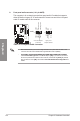


Table Of Contents
- Safety information
- About this guide
- P8H77-V specifications summary
- Chapter 1: Product introduction
- Chapter 2: Hardware information
- 2.1 Before you proceed
- 2.2 Motherboard overview
- 2.3 Building your computer system
- 2.3.1 Additional tools and components to build a PC system
- 2.3.2 CPU installation
- 2.3.3 CPU heatsink and fan assembly installation
- 2.3.4 DIMM installation
- 2.3.5 Motherboard installation
- 2.3.6 ATX Power connection
- 2.3.7 SATA device connection
- 2.3.8 Front I/O Connector
- 2.3.9 Expension Card installation
- 2.3.10 Rear panel connection
- 2.3.11 Audio I/O connections
- 2.4 Starting up for the first time
- 2.5 Turning off the computer
- Chapter 3: BIOS setup
- Chapter 4: Software support
- Chapter 5: Multiple GPU technology support
- Appendices
- http://csr.asus.com/english/Takeback.htm
2-24
Chapter 2: Hardware information
Chapter 2
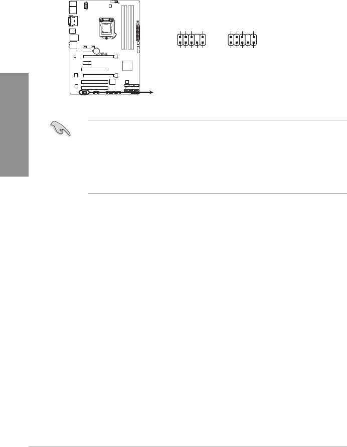
8. Front panel audio connector (10-1 pin AAFP)
This connector is for a chassis-mounted front panel audio I/O module that supports
either HD Audio or legacy AC`97 audio standard. Connect one end of the front panel
audio I/O module cable to this connector.
• We recommend that you connect a high-denition front panel audio module to this
connector to avail of the motherboard’s high-denition audio capability.
• If you want to connect a high-denition front panel audio module to this connector,If you want to connect a high-denition front panel audio module to this connector,
set the
Front Panel Type
item in the BIOS setup to
[HD];
if you want to connect an
AC'97 front panel audio module to this connector, set the item to
[AC97]
. By default,
this connector is set to
[HD]
. See section
3.5.6 Onboard Devices Conguration
for
details.
P8H77-V
P8H77-V Front panel audio connector
AAFP
PIN 1
AGND
NC
SENSE1_RETUR
SENSE2_RETUR
PORT1 L
PORT1 R
PORT2 R
SENSE_SEND
PORT2 L
HD-audio-compliant
pin definition
PIN 1
AGND
NC
NC
NC
MIC2
MICPWR
Line out_R
NC
Line out_L
Legacy AC’97
compliant definition