
user manual


Table Of Contents
- Safety information
- About this guide
- P8H77-V specifications summary
- Chapter 1: Product introduction
- Chapter 2: Hardware information
- 2.1 Before you proceed
- 2.2 Motherboard overview
- 2.3 Building your computer system
- 2.3.1 Additional tools and components to build a PC system
- 2.3.2 CPU installation
- 2.3.3 CPU heatsink and fan assembly installation
- 2.3.4 DIMM installation
- 2.3.5 Motherboard installation
- 2.3.6 ATX Power connection
- 2.3.7 SATA device connection
- 2.3.8 Front I/O Connector
- 2.3.9 Expension Card installation
- 2.3.10 Rear panel connection
- 2.3.11 Audio I/O connections
- 2.4 Starting up for the first time
- 2.5 Turning off the computer
- Chapter 3: BIOS setup
- Chapter 4: Software support
- Chapter 5: Multiple GPU technology support
- Appendices
- http://csr.asus.com/english/Takeback.htm
ASUS P8H77-V
2-17
Chapter 2
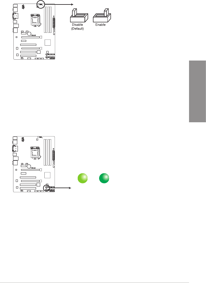
2. GPU Boost switch
This switch allows you to enable or disable the GPU Boost function.
P8H77-V
P8H77-V GPU Boost switch
GPU Boost
2.2.7 Onboard LEDs
1. Standby Power LED
The motherboard comes with a standby power LED that lights up to indicate that the
system is ON, in sleep mode, or in soft-off mode. This is a reminder that you should
shut down the system and unplug the power cable before removing or plugging in any
motherboard component. The illustration below shows the location of the onboard LED.
SB_PWR
ON
Standby Power Powered Of
f
OFF
P8H77-V
P8H77-V Onboard LED