
user manual


Table Of Contents
- Safety information
- About this guide
- P8H77-V specifications summary
- Chapter 1: Product introduction
- Chapter 2: Hardware information
- 2.1 Before you proceed
- 2.2 Motherboard overview
- 2.3 Building your computer system
- 2.3.1 Additional tools and components to build a PC system
- 2.3.2 CPU installation
- 2.3.3 CPU heatsink and fan assembly installation
- 2.3.4 DIMM installation
- 2.3.5 Motherboard installation
- 2.3.6 ATX Power connection
- 2.3.7 SATA device connection
- 2.3.8 Front I/O Connector
- 2.3.9 Expension Card installation
- 2.3.10 Rear panel connection
- 2.3.11 Audio I/O connections
- 2.4 Starting up for the first time
- 2.5 Turning off the computer
- Chapter 3: BIOS setup
- Chapter 4: Software support
- Chapter 5: Multiple GPU technology support
- Appendices
- http://csr.asus.com/english/Takeback.htm
ASUS P8H77-V
2-3
Chapter 2
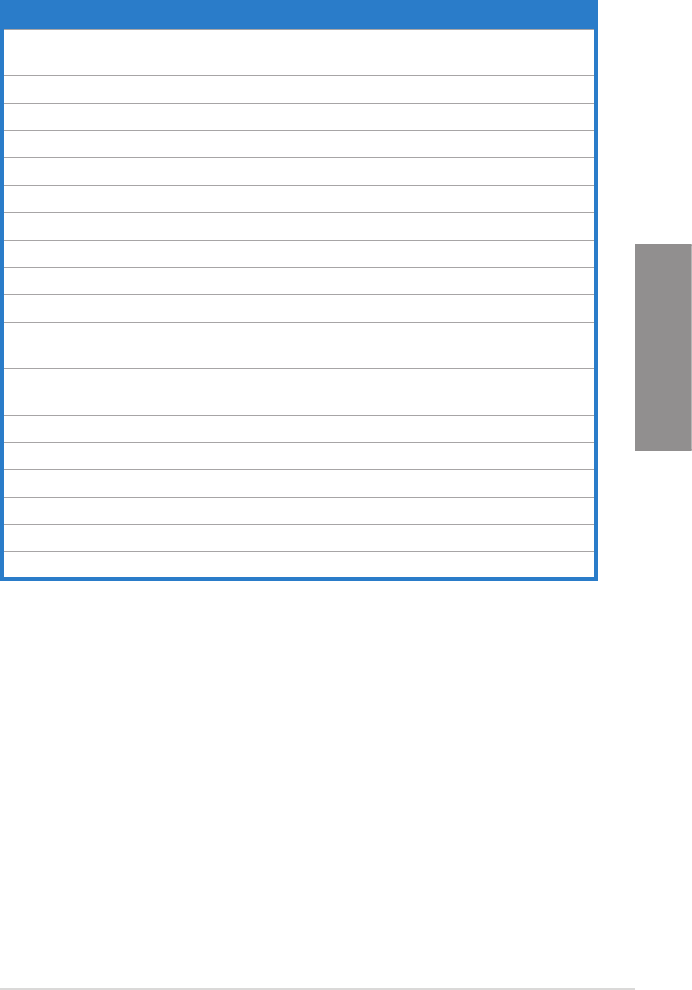
Layout contents
Connectors/Jumpers/Slots Page
1. CPU, chassis, and power fan connectors (4-pin CPU_FAN,
4-pin CHA_FAN1/2, 3-pin PWR_FAN)
2-23
2. ATX power connectors (24-pin EATXPWR, 8-pin EATX12V) 2-25
3. Intel
®
LGA1155 CPU socket 2-4
4. GPU Boost switch 2-17
5. GPU Boost LED 2-18
6. DDR3 DIMM slots 2-5
7. MemOK! switch 2-16
8. DRAM LED (DRAM_LED) 2-18
9. USB 3.0 connector (20-1 pin USB3_34) 2-21
10. Onboard LED (SB_PWR) 2-17
11. Intel
®
H77 Serial ATA 3.0Gb/s connectors
(7-pin SATA3G_1~4 [blue])
2-20
12. Intel
®
H77 Serial ATA 6.0Gb/s connectors
(7-pin SATA6G_1/2 [gray])
2-19
13. System panel connector (20-8 pin PANEL) 2-26
14. Clear RTC RAM (3-pin CLRTC) 2-15
15. USB 2.0 connectors (10-1 pin USB56, USB78, USB910) 2-21
16. Serial port connector (10-1 pin COM1) 2-22
17. Front panel audio connector (10-1 pin AAFP) 2-24
18. Digital audio connector (4-1 pin SPDIF_OUT) 2-22