R P2L-VM/P2E-VM Pentium II microATX Motherboard ® USER’S MANUAL
USER'S NOTICE No part of this manual, including the products and software described in it, may be reproduced, transmitted, transcribed, stored in a retrieval system, or translated into any language in any form or by any means, except documentation kept by the purchaser for backup purposes, without the express written permission of ASUSTeK COMPUTER INC. (“ASUS”).
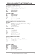
ASUS CONTACT INFORMATION ASUSTeK COMPUTER INC. Marketing Address: Telephone: Fax: Email: 150 Li-Te Road, Peitou, Taipei, Taiwan 112 +886-2-2894-3447 +886-2-2894-3449 info@asus.com.tw Technical Support Fax: BBS: Email: WWW: FTP: +886-2-2895-9254 +886-2-2896-4667 tsd@asus.com.tw www.asus.com.tw ftp.asus.com.tw/pub/ASUS ASUS COMPUTER INTERNATIONAL Marketing Address: Fax: Email: 6737 Mowry Avenue, Mowry Business Center, Building 2 Newark, CA 94560, USA +1-510-608-4555 info-usa@asus.com.
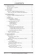
CONTENTS I. INTRODUCTION ........................................................................... 7 How this manual is organized .......................................................... 7 Item Checklist .................................................................................. 7 II. FEATURES .................................................................................... 8 ASUS P2L-VM/P2E-VM Motherboard Features ............................ 8 Parts of the ASUS P2L-VM/P2E-VM Motherboard ....
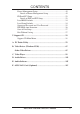
CONTENTS Power Management Setup .......................................................... Details of Power Management Setup ................................... PNP and PCI Setup .................................................................... Details of PNP and PCI Setup .............................................. Load BIOS Defaults ................................................................... Load Setup Defaults ...................................................................
FCC & DOC COMPLIANCE Federal Communications Commission Statement This device complies with FCC Rules Part 15. Operation is subject to the following two conditions: • • This device may not cause harmful interference, and This device must accept any interference received, including interference that may cause undesired operation. This equipment has been tested and found to comply with the limits for a Class B digital device, pursuant to Part 15 of the FCC Rules.
I. INTRODUCTION I. INTRODUCTION Manual / Checklist How this manual is organized This manual is divided into the following sections: I. II. III. IV. V. Introduction: Features: Installation: BIOS Software: Support CD: Manual information and checklist Information and specifications concerning this product Instructions on setting up the motherboard Instructions on setting up the BIOS software Information on the included support software Item Checklist Please check that your package is complete.
II. FEATURES ASUS P2L-VM/P2E-VM Motherboard Features The ASUS P2L-VM/P2E-VM motherboard is carefully designed for the demanding PC user who wants many features in a small package. II. FEATURES Features ASUS P2L-VM/P2E-VM Specifications: • microATX: Features ASUS’ custom designed microATX form factor. • Multi-Speed: Supports the Intel Pentium® II (233MHz–333MHz) and Celeron™ (266MHz and faster) processors. • Intel AGPset: Features Intel’s 440LX or 440EX AGPset with I/O subsystems.
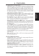
II. FEATURES II. FEATURES Features ASUS P2L-VM/P2E-VM Special Features: • ACPI Ready: Features ACPI (Advanced Configuration and Power Interface) which is also implemented on all ASUS “smart” series motherboards. ACPI provides more Energy Saving Features for future operating systems (OS) supporting OS Direct Power Management (OSPM) functionality. With these features implemented in the OS, PCs can be ready around the clock, yet satisfy all the energy saving standards.
II. FEATURES II. FEATURES Features ASUS P2L-VM/P2E-VM Intelligence • Auto Fan Off: The system fans will power off automatically even in sleep mode. This function reduces both energy consumption and system noise, and is an important feature to implement silent PC systems. • Boot Virus Protection: Anti-boot virus protection programmed into the BIOS. • Dual Function Power Button: The system can be in one of two states, one is the sleep mode and the other is the Soft-Off mode.
II. FEATURES Parts of the ASUS P2L-VM/P2E-VM Motherboard ATI Multimedia Connector 2 DIMM on 440EX 3 DIMM on 440LX ATX Power Power Supply Fan Control ImpacTV2 8MB VGA ATI 3D Rage Pro AGP 2X VGA Chipset (optional) Memory II.
III.
III. INSTALLATION Jumpers 1) 2) 3) 4) 5) 6) INT_EN VGAEN CLRCMOS KBPWR FS0, FS1, FS2 BF0, BF1, BF2, BF3 p. 14 VGA Interrupt Setting (Enable/Disable) p. 14 VGA Setting (Enable/Disable) p. 15 Real Time Clock RAM (Clear CMOS) p. 15 Keyboard Power Up (Enable/Disable) p. 16 CPU External Clock (BUS) Frequency Selection p. 16 CPU:BUS Frequency Ratio Expansion Slots 1) 2) 3) 4) DIMM Sockets SEC CPU Slot ISA Slot 1, 2 PCI Slot 1, 2, 3 p. 17 p. 19 p. 25 p.
III. INSTALLATION Installation Steps Before using your computer, you must complete the following steps: 1. 2. 3. 4. 5. 6. Set Jumpers on the Motherboard Install System Memory Modules Install the Central Processing Unit (CPU) Install Expansion Cards Connect Ribbon Cables, Cabinet Wires, and Power Supply Setup the BIOS Software III. INSTALLATION Jumpers WARNING! Computer motherboards, baseboards and components, such as SCSI cards, contain very delicate Integrated Circuit (IC) chips.
III. INSTALLATION 3. Real Time Clock (RTC) RAM (CLRCMOS) The CMOS RAM is powered by the onboard button cell battery. To clear the RTC data: (1) Unplug your computer, (2) Short solder points, (3) Turn on your computer, (4) Hold down during bootup and enter BIOS setup to reenter user preferences. RTC RAM CLRCMOS Clear CMOS [short solder points momentarily] III. INSTALLATION Jumpers R CLRCMOS P2L-VM/P2E-VM Clear RTC RAM 4.
III. INSTALLATION 5. CPU External (BUS) Frequency Selection (FS0, FS1, FS2) These jumpers tell the clock generator what frequency to send to the CPU. These allow the selection of the CPU’s External frequency (or BUS Clock). The BUS Clock times the BUS Ratio equals the CPU's Internal frequency (the advertised CPU speed). 6.
III. INSTALLATION 2. System Memory (DIMM) Only Dual Inline Memory Modules (DIMM) can be used with this motherboard. Sockets are available for 3.3Volt (power level) Unbuffered Synchronous DRAMs (SDRAM) or EDO DRAM of either 8, 16, 32, 64, or 128MB. One side (with memory chips) of the DIMM module takes up one Row on the motherboard.
III. INSTALLATION DIMM Memory Installation Insert the module(s) as shown. Because the number of pins are different on either side of the breaks, the module will only fit in the orientation as shown. DIMM modules are longer and have different pin contact on each side and therefore have a higher pin density. SIMM modules have the same pin contact on both sides. III. INSTALLATION System Memory 20 Pins 60 Pins R 88 Pins Lock P2L-VM/P2E-VM 168-Pin DIMM Sockets The DIMMs must be 3.
III. INSTALLATION 3. Central Processing Unit (CPU) This motherboard provides a Single Edge Contact (SEC) slot for a Pentium II processor packaged in an SEC cartridge. Pentium II Processor WARNING! Be sure that sufficient air is circulating across the processor’s passive heatsink. Without sufficient circulation, the processor could overheat and damage both the processor and the motherboard. It is recommended that you install an auxiliary fan. III.
III. INSTALLATION The Motherboard As Shipped Four screws should be showing next to each corner of the SEC CPU Slot using two attach mount bridges from the underside of the motherboard. (1) SEC CPU slot NOTE: Encircled items are screws from the mount bridges (1 & 2) (2) III. INSTALLATION CPU Installing the Pentium II Processor: 1. Mount the Pentium II Retention Mechanism: The retention mechanism is designed to fit into the SEC slot only one way.
III. INSTALLATION 2. Mount the Heatsink: Place the SEC cartridge face down on a flat surface and lay the heat sink flush on the back (metal side) of the SEC cartridge. Check the orientation of the heatsink against the pictures. The thicker fin must be orientated toward the bottom. The top clamp is wider than the bottom clamp so only this orientation will fit. With a screw driver, push the clamps one at a time into the SEC cartridge. Be sure that the heatsink is firmly pressed against the SEC cartridge.
III. INSTALLATION 4. Secure the SEC Cartridge: Secure the SEC cartridge in place by pushing the SEC cartridge locks outward so that the lock shows through the retention mechanism’s lock holes. (3) (3) (8) III. INSTALLATION CPU 5. Secure the Heatsink: Install the heatsink support base into the motherboard. This is not, however, necessary if you use a heatsink with fan (see next page). The support base is necessary to secure the heatsink (without fan).
III. INSTALLATION The heatsinks shown in this manual are for reference purposes only. The recommended heatsinks for the Pentium II processor are those with three-pin fans that can be connected to the CPU fan connector on the motherboard. These heatsinks have the added benefits of proper heat dissipation and with the hardware monitor, the ability to monitor the fan’s RPM and use the alert function through the included LANDesk Client Manager (LDCM) software. III.
III. INSTALLATION 4. Expansion Cards WARNING! Unplug your power supply when adding or removing expansion cards or other system components. Failure to do so may cause severe damage to both your motherboard and expansion cards. Expansion Card Installation Procedure III. INSTALLATION Expansion Cards 1. Read the documentation for your expansion card and make any necessary hardware or software settings for your expansion card, such as jumpers. 2.
III. INSTALLATION To simplify this process, this motherboard has complied with the Plug and Play (PNP) specification which was developed to allow automatic system configuration whenever a PNP-compliant card is added to the system. For PNP cards, IRQs are assigned automatically from those available. If the system has both Legacy and PNP ISA cards installed, IRQs are assigned to PNP cards from those not used by Legacy cards.
III. INSTALLATION 5. External Connectors WARNING! Some pins are used for connectors or power sources. These are clearly distinguished from jumpers in the Motherboard Layout. Placing jumper caps over these connector pins will cause damage to your motherboard. IMPORTANT: Ribbon cables should always be connected with the red stripe on the Pin 1 side of the connector. The four corners of the connectors are labeled on the motherboard.
III. INSTALLATION 3. Parallel Port Connector (25-pin Female) You can enable the parallel port and choose the IRQ through “Onboard Parallel Port” in Chipset Features Setup of the BIOS SOFTWARE. NOTE: Serial printers must be connected to the serial port. Parallel (Printer) Port (25-pin Female) III. INSTALLATION DMA Connectors Channels 4. Serial Port COM1 Connector (9-pin Male) One serial port is ready for a mouse or other serial devices.
III. INSTALLATION 6. Audio Port Connectors (Three 1/8” Female) (with optional onboard audio) Line Out can be connected to headphones or preferably powered speakers. Line In allows tape players or other audio sources to be recorded by your computer or played through the Line Out. Mic allows microphones to be connected for inputing voice. Line Out Line In Mic 1/8" Stereo Audio Connectors III. INSTALLATION Connectors 7.
III. INSTALLATION 9. Primary / Secondary IDE connectors (Two 40-1pin IDE) These connectors support the provided IDE hard disk ribbon cable. After connecting the single end to the board, connect the two plugs at the other end to your hard disk(s). If you install two hard disks, you must configure the second drive to Slave mode by setting its jumper accordingly. Please refer to the documentation of your hard disk for the jumper settings.
III. INSTALLATION 11. Floppy Disk Drive Connector (34-1pin FLOPPY) This connector supports the provided floppy drive ribbon cable. After connecting the single end to the board, connect the two plugs on the other end to the floppy drives. (Pin 5 is removed to prevent inserting in the wrong orientation when using ribbon cables with pin 5 plugged). NOTE: Orient the red markings on the floppy ribbon cable to PIN 1 R PIN 1 Floppy Disk Drive Connector P2L-VM/P2E-VM Floppy Disk Drive Connector III.
III. INSTALLATION 14. IrDA / Fast IR-Compliant infrared module connector (5-pin IR) This connector supports the optional wireless transmitting and receiving infrared module. This module mounts to a small opening on system cases that support this feature. You must also configure the setting through “UART2 Use Infrared” in Chipset Features Setup to select whether UART2 is directed for use with COM2 or IrDA.
III. INSTALLATION III. INSTALLATION Connectors 16. Message LED Lead (LED, 2 pins) This indicates whether a message has been received from a fax/modem. The LED will remain lit when there is no signal and blink when data are being transfer or messages are waiting in the inbox. This function requires ACPI OS support. 17.
III. INSTALLATION 23. Chassis, CPU , & Power Supply Fan Connectors (3-pin CHA_, CPU_, PWR_FAN) These connectors support cooling fans of 500mAMP (6 Watts) or less. Orientate the fans so that the heat sink fins allow airflow to go across the onboard heat sink(s) instead of the expansion slots. Depending on the fan manufacturer, the wiring and plug may be different. The red wire should be positive, while the black should be ground.
III. INSTALLATION Power Requirement It is important that your power supply exceeds the power consumption of all devices connected to your power supply especially when upgrading your processor. The following table shows the approximate power consumption of this motherboard with 64MB SDRAM using different processors running a Winstone98 demo, playing an audio CD, and playing a MIDI file simultaneously. Processor Celeron Klamath233 Klamath266 Klamath300 Deschutes333 +5V 4.5A 7.8A 8.7A 8.7A 5.1A +12V 0.36A 0.
III. INSTALLATION Power Connection Procedures 1. After all connections are made, close the system case cover. 2. Be sure that all switches are off (in some systems, marked with ). 3. Connect the power supply cord into the power supply located on the back of your system case according to your system user’s manual. 4. Connect the power cord into a power outlet that is equipped with a surge protector. III. INSTALLATION Power Connections 5. You may then turn on your devices in the following order: a.
IV. BIOS SOFTWARE Support Software AFLASH.EXE: This is the Flash Memory Writer utility that updates the BIOS by uploading a new BIOS file to the programmable flash ROM chip on the motherboard. To determine the BIOS version of your motherboard, check the last four numbers of the code displayed on the upper left-hand corner of your screen during bootup. Larger numbers represent a newer BIOS file. This file works only in DOS mode.
IV. BIOS SOFTWARE 2. Update BIOS Including Boot Block and ESCD This option updates the boot block, the baseboard BIOS, and the ACPI extended system configuration data (ESCD) parameter block from a new BIOS file. See the next page for procedures on downloading an updated BIOS file. To update your current BIOS, type [2] at the Main Menu and then press . The Update BIOS Including Boot Block and ESCD screen appears. Type the filename of your new BIOS and the path, for example, A:\XX2I1002.
IV. BIOS SOFTWARE Managing and Updating Your Motherboard’s BIOS Upon First Use of the Computer System 1. Create a bootable system floppy disk by typing [FORMAT A:/S] from the DOS prompt without creating “AUTOEXEC.BAT” and “CONFIG.SYS” files. 2. Copy AFLASH.EXE to the just created boot disk. 3. Run AFLASH.EXE from this new disk and select option 1. Save Current BIOS to File. See 1. Save Current BIOS To File on the previous page for more details and the rest of the steps.
IV. BIOS SOFTWARE 6. BIOS Setup This motherboard supports one programmable Flash ROM chip of 5 Volt which can be updated when BIOS upgrades are released. Use the Flash Memory Writer utility to download the new BIOS file into the ROM chip as described in detail in this section. All computer motherboards provide a Setup utility program for specifying the system configuration and settings. If your motherboard came in a computer system, the proper configuration entries may have already been made.
IV. BIOS SOFTWARE Load Defaults The “Load BIOS Defaults” option loads the minimum settings for troubleshooting. “Load Setup Defaults”, on the other hand, is for loading optimized defaults for regular use. Choosing defaults at this level, will modify all applicable settings. Standard CMOS Setup The “Standard CMOS Setup” option allows you to record some basic system hardware configuration and set the system clock and error handling.
IV. BIOS SOFTWARE Time To set the time, highlight the “Time” field and then press either / or <+>/<–> to set the current time. Follow the hour, minute and second format. Valid values for hour, minute and second are: (Hour: (00 to 23), Minute: (00 to 59), Second: (00 to 59). Press twice if you do not want to modify the current time. NOTE: You can bypass the date and time prompts by creating an AUTOEXEC.BAT file.
IV. BIOS SOFTWARE Auto detection of hard disks on bootup For each field: Primary Master, Primary Slave, Secondary Master, and Secondary Slave, you can select Auto under the TYPE and MODE fields. This will enable auto detection of your IDE hard disk during bootup. This will allow you to change your hard disks (with the power off) and then power on without having to reconfigure your hard disk type.
IV. BIOS SOFTWARE BIOS Features Setup The “BIOS Features Setup” option consists of configuration entries that allow you to improve your system performance, or let you set up some system features according to your preference. Some entries are required by the motherboard’s design to remain in their default settings. IV. BIOS BIOS Features A section at the lower right of the screen displays the control keys you can use. Take note of these keys and their respective uses.
IV. BIOS SOFTWARE CPU Level 1 Cache / CPU Level 2 Cache (Enabled) These fields allow you to choose from the default of Enabled or choose Disabled to turn on or off the CPU’s Level 1 and Level 2 built-in cache. CPU Level 2 Cache ECC Check (Disabled) Enabled allows the system to run an ECC check on the Level 2 cache. This is Disabled because this feature slows performance. BIOS Update (Enabled) This functions as an update loader integrated into the BIOS to supply the processor with the required data.
IV. BIOS SOFTWARE PS/2 Mouse Function Control (Auto) The default of Auto allows the system to detect a PS/2 mouse on bootup. If detected, IRQ12 will be used for the PS/2 mouse. IRQ12 will be reserved for expansion cards if a PS/2 mouse is not detected. Enabled will always reserve IRQ12, whether on bootup a PS/2 mouse is detected or not.
IV. BIOS SOFTWARE Chipset Features Setup This “Chipset Features Setup” option controls the configuration of the board’s chipset. Control keys for this screen are the same as for the previous screen. NOTE: SETUP Defaults are noted in parenthesis next to each function heading. Details of Chipset Features Setup EDO Auto Configuration (60ns DRAM) The default setting of 60ns DRAM sets the optimal timings for items 2 through 5 for 60ns DRAM modules.
IV. BIOS SOFTWARE Video Memory Cache Mode (UC) USWC (uncacheable, speculative write combining) is a new cache technology for the video memory of the processor. It can greatly improve the display speed by caching the display data. You must leave this on the default setting of UC (uncacheable) if your display card cannot support this feature or else your system may not boot. PCI 2.1 Support (Enabled) This function allows you to Enable or Disable PCI 2.1 features. Leave on Enabled setting for PCI 2.
IV. BIOS SOFTWARE Onboard FDC Swap A & B (No Swap) This field allows you to reverse the hardware drive letter assignments of your floppy disk drives. Two options are available: No Swap and Swap AB. If you want to switch drive letter assignments through the onboard chipset, set this field to Swap AB. Onboard Serial Port 1 (3F8H/IRQ4) Settings are 3F8H/IRQ4, 2F8H/IRQ3, 3E8H/IRQ4, 2E8H/IRQ10, and Disabled for the onboard serial connector.
IV. BIOS SOFTWARE Power Management Setup The “Power Management Setup” option allows you to reduce power consumption. This feature turns off the video display and shuts down the hard disk after a period of inactivity. NOTE: SETUP Defaults are noted in parenthesis next to each function heading. Details of Power Management Setup IV. BIOS Power Management Power Management (User Define) This field acts as the master control for the power management modes.
IV. BIOS SOFTWARE Video Off Method (DPMS OFF) This field defines the video off features. The following options are available: DPMS OFF, DPMS Reduce ON, Blank Screen, V/H SYNC+Blank, DPMS Standby, and DPMS Suspend. The DPMS (Display Power Management System) features allow the BIOS to control the video display card if it supports the DPMS feature. Blank Screen only blanks the screen (use this for monitors without power management or “green” features.
IV. BIOS SOFTWARE PWR Up On Modem Act (Enabled) This allows either settings of Enabled or Disabled for powering up the computer (turns the ATX power supply on) when the modem receives a call while the computer is off. NOTE: The computer cannot receive or transmit data until the computer and applications are fully running, thus connection cannot be made on the first try.
IV. BIOS SOFTWARE PNP and PCI Setup This “PNP and PCI Setup” option configures the PCI bus slots. All PCI bus slots on the system use INTA#, thus all installed PCI cards must be set to this value. NOTE: SETUP Defaults are noted in parenthesis next to each function heading. Details of PNP and PCI Setup IV. BIOS Plug & Play / PCI PNP OS Installed (No) This field allows you to use a Plug-and-Play (PnP) operating system to configure the PCI bus slots instead of using the BIOS.
IV. BIOS SOFTWARE DMA x Used By ISA (No/ICU) These fields indicate whether or not the displayed DMA channel for each field is being used by a legacy (non-PnP) ISA card. Available options include: No/ICU and Yes. The first option, the default setting, indicates either that the displayed DMA channel is not used or an ICU is being used to determine if an ISA card is using that channel.
IV.
IV. BIOS SOFTWARE Supervisor Password and User Password IV. BIOS Passwords Two options set the system passwords. “Supervisor Password” sets a password that will be used to protect the system and the Setup utility; “User Password” sets a password that will be used exclusively on the system. By default, the system comes without any passwords. To specify a password, highlight the type you want and then press . A password prompt appears on the screen.
IV. BIOS SOFTWARE IDE HDD Auto Detection The “IDE HDD Auto Detection” option detects the parameters of an IDE hard disk drive, and automatically enters them into the Standard CMOS Setup screen. IV. BIOS Hard Disk Detect Up to four IDE drives can be detected, with parameters for each listed inside the box. To accept the optimal entries, press or else select from the numbers displayed under the OPTIONS field (2, 1, 3 in this case); to skip to the next drive, press .
IV. BIOS SOFTWARE IMPORTANT: If your hard disk was already formatted on an older previous system, incorrect parameters may be detected. You will need to enter the correct parameters manually or use low-level format if you do not need the data stored on the hard disk. If the parameters listed differ from the ones used when the disk was formatted, the disk will not be readable. If the auto-detected parameters do not match the ones that should be used for your disk, do not accept them.
V. Support CD Support CD Main Menu Insert your CD or double click on your CD drive icon in “My Computer” to bring up the autorun menu or run Setup.exe in the root directory of the ASUS Support CD. NOTE: The support CD version and contents are constantly updated without notice. V. SOFTWARE ASUS Support CD Main Menu Selections LDCM Local Setup: Installs the LANDesk Client Manager software to monitor the local system.
A. PC Probe Utility User’s Manual R PC Probe USER’S MANUAL Included only with products using hardware monitoring components.
A. PC Probe Utility A. PC Probe Utility Installing / Running Installing and Running ASUS PC Probe The ASUS PC Probe is a convenient utility to monitor the computer system’s vital components: fan rotations, voltages, and temperatures. NOTE: In order for the ASUS PC Probe to run, Intel’s LDCM utility cannot be installed. 1. Click on “ASUS PC Probe Setup” from the main menu. 2. Click “OK” after reading the welcome message. 3. Click the install button. 4. Make any desired setting changes. 5.
A. PC Probe Utility A. PC Probe Utility Uninstalling Uninstalling Programs Uninstalling programs is a basic component within Windows 95. You may use this function if individual programs does not provide their own uninstallation methods. 1. If other hardware monitoring programs such as the Intel LDCM are installed, the ASUS PC Probe will not run. 2. Uninstall other hardware monitoring programs if you want to use the ASUS PC Probe by running “Add/Remove Programs” from the Control Panel. 3.
A. PC Probe Utility A.
A. PC Probe Utility A. PC Probe Utility Using PC Probe Using the ASUS PC Probe PC Probe System Info. Get information on your mainboard and BIOS from this screen. PC Probe Settings Change PC Probe refresh times here Check here to start PC Probe each time you enter Windows. Check the items above you wish to reset to its default values and click this button. PC Probe Task Bar Icon Right clicking the “doctor” will bring up a menu to turn ASUS PC Probe on, off, or exit the utility.
(This page was intentionally left blank) 64 ASUS P2L-VM/P2E-VM User’s Manual
B. Video Driver B. Video Driver .................................................................. 65 65 66 67 67 68 69 71 73 73 74 74 76 77 77 77 78 78 79 79 80 82 B. Video Driver Contents First Time Installation ................................................................ Install Windows 95 Display Driver ................................................. Install DirectX .................................................................................. Install Video Player ...........................
B. Video Driver Troubleshooting ......................................................................... Windows 95 mach64 enhanced display driver ..................... Windows 95 property page problems ................................... ATI Video Player Notes ........................................................ Other Problems & Actions .................................................... 93 95 95 95 96 C. Video Player .................................................................. 97 B.
B. Video Driver First Time Installation When starting Windows 95 (OSR2.0) or Windows 98, the operating system will detect that you have a new PCI Multimedia Device, then an Update Device Driver Wizard will appear. B. Video Driver First Time Install Click the Next button. Click Other Locations button to direct the wizard to the audio driver files. Click the Browse button to locate the “\DRIVERS\ATI435\WIN95” (or WIN98) directory on the ASUS Support CD.
B. Video Driver Install Windows 95 Display Driver Install Windows 95 Display Driver allows your onboard VGA to function properly. B. Video Driver Display Driver Reinsert your CD or double click on your CD drive icon in My Computer to bring up the autorun screen or run Setup.exe in the root directory of the CD. Click 95 Video Driver from the main menu. Click Install Windows 95 Display Driver to begin the installation wizard. The “ATI 3D” setup screen will appear. Click Next to complete your installation.
B. Video Driver Install DirectX Microsoft DirectX allows Direct3D support in Windows. B. Video Driver DirectX / Video Player Reinsert your CD or double click on your CD drive icon in My Computer to bring up the autorun screen or run Setup.exe in the root directory of the CD. Click 95 Video Driver from the main menu. Click Install DirectX5 to begin installation. Warning: Your computer will automatically restart without warning.
B. Video Driver Display Settings for Windows 95 Changing display settings: To enter the “Display Properties” at any time, right click your mouse on the desktop and select “Properties” or double click the “Display” icon in the “Control Panel.” Click the appropriate Tab as follows: Adjustment: Click on the Position or Size arrows to make your screen appear as centered and large as possible. B.
B. Video Driver Video Driver Installation for Windows 3.x For your convenience, the ATI video drivers for Windows 3.x can be installed in Windows 3.x or in DOS. The autorun ASUS Windows 3.1 Install Shell cannot be automatically run by Window 3.x, so manual execution is necessary. B. Video Driver Windows 3.x Installing ATI video drivers in Windows 3.x: 1. Start Windows 3.x 2. Run File Manager 3. Insert the ASUS installation CD. 4. Change to your CD drive. 5. Double click setup.exe - ASUS Windows 3.
B. Video Driver Video Driver Installation for Windows 3.x Installing ATI video drivers in DOS: 1. Enter DOS mode (Exit Windows, do not use Windows DOS prompt) 2. Change to your CD-ROM drive 3. Type: SETUP (assuming your CD-ROM drive is letter D) in DOS mode. ASUS DOS installation shell will appear and present you with a list of install option. B. Video Driver Windows 3.x 4. Press Enter to confirm path of Windows 3.x or change if necessary. 5. “ASUS driver is successfully installed !!” - press any key. 6.
B. Video Driver Software MPEG & Video Player for Windows 3.x B. Video Driver Windows 3.x Software MPEG allows the viewing of the following video files identified by their extensions: • MPEG Format: (*.MPG, *.DAT, *.MPV) Extensions • AVI Files (*.AVI) Extensions For Software MPEG support in Windows 3.x, you must first install Microsoft’s Video for Windows, then install ATI Video Player. Installing Microsoft Video for Windows in Windows 3.x: 1. Click on Install Video for Windows - Video for Windows 1.
(This page was intentionally left blank) 74 ASUS P2L-VM/P2E-VM User’s Manual
B. Video Driver NOTE: This section shows screens for Windows 3.1x although feature descriptions may be used for both Windows 3.1x and Windows 95. ATI Desktop Control Panel B. Video Driver Windows 3.x An ATI DeskTop is installed automatically when you install the enhanced driver for Windows. Double click on the icon to display the ATI Desktop Control Panel. The ATI DeskTop provides a consistent and integrated control.
B. Video Driver FlexDesk+ B. Video Driver Windows 3.x FlexDesk+ Basic Settings FlexDesk+ is for configuring the operating modes and parameters of the ASUS 264 Series Device. The availability of options in FlexDesk+ is dependent on the device and its hardware configuration. This control panel allows you to configure Colors (color depth), Screen Size (resolution), Desktop Size (virtual desktop size), Advanced settings and Default parameters (factory settings).
B. Video Driver Buttons Test: Automatically switches on monitor to display the selected mode without exiting this control panel, for 10 seconds or until the user clicks the End Test, OK, or Cancel button. All other buttons and sliders are inactive at this time. To show dynamic color depth changes in this test, the WinSwitch feature must by enabled before starting the current session of Windows. B. Video Driver Windows 3.
B. Video Driver FlexDesk+ Advanced Settings B. Video Driver Windows 3.x Environment This parameter specifies logical dots per inch (LDPI). Being logical, i.e., not physical dots, the effect will differ depending on screen size. Automatic Mode chooses the optimal environment setting for the selected screen size. The Small, Large and DTP settings are 96, 120, and 128 LDPI respectively. 256 Color Palette This selection is only available in 256 color mode. Windows runs faster when this option is turned off.
B. Video Driver DPMS (for Windows) B. Video Driver Windows 3.x Win3.1 Limitation: In some newer BIOS, DPMS fucntion doesn't work normally. VESA DPMS-compliant monitors conserve electrical energy by powering down after a period of inactivity. You can use the DPMS panel (in Windows) to configure the auto-shutdown timing sequence for your DPMS-compliant monitor. (The DOS version of DPMS is described in another section.
B. Video Driver DeskScape B. Video Driver Windows 3.x NOTE: Press Default to fill in the fields with default keys first. DeskScape allows more control over your Virtual Desktop using keyboard keys. For a description of Screen and Desktop, Refer to the Using FlexDesk+ section. The displayed image on the screen is a "window" showing only a portion of the entire virtual desktop. The non-displayed portion can be brought into view by panning.
B. Video Driver Buttons Defaults: Assigns default keys to DeskScan. Help: Displays Help information on DeskScan. OK: Accepts key assignments as shown and exits. Cancel: Discards all changes and exits. B. Video Driver Windows 3.x WinSwitch NOTE: Press Default to fill in the fields with default keys first. By pressing a user-defined set of keyboard keys WinSwitch can dynamically change screen attributes (i.e., Colors, Screen Size and Desktop Size) without exiting Windows.
B. Video Driver Buttons Key 1: First of four radio buttons labeled key1, key 2, key 3, and key 4. The slider settings shown are associated with the selected radio button. Defaults: Restores key combination and slider settings to defaults. Help: Displays Help information on WinSwitch. OK: Accepts current settings and exits. B. Video Driver Windows 3.x Cancel: Discards all changes and exits. WinSwitch: Switching function is enabled when the box is Checked; disabled when the box is empty.
B. Video Driver Windows 3.x B. Video Driver If your monitor came with a VDIF file then you may insert it into your floppy drive and press the "Load VDIF" button. The "Custom" button allows you to select the resolution and refresh rates. You may try out different settings that will optimize your display preferences but too high of a refresh rate will push your monitor past its specifications. Use the Preview/Adjust to see the results and allow digital adjustments to the screen.
B. Video Driver The ASUS 264 Series Device supports a VESA power management control specification called DPMS-Display Power Management Signaling. Monitors that comply with DPMS can provide energy savings up to 80% compared to non DPMS compliant monitors. This also translates into extended monitor life. DPMS control functions are provided for DOS and Windows operations. This chapter describes the DOS version, a Terminate-and-Stay-Resident program. TSR means it runs in the background once activated.
B. Other Video Drivers Video Driver Installation for Windows NT 4.0 B. Other Video Drivers Windows NT 4.0 IMPORTANT! • Windows NT 3.5x does not support AGP cards. • Before installing the ASUS display driver in Windows NT 4.0, make sure that you have installed Windows NT 4.0 Service Pack version 3.0 (available on the Internet at http://www.microsoft.com/isapi/support/bldqpage.idc?Product Page=q_servpk).
B. Other Video Drivers Video Driver Installation for Windows NT 4.0 Installing ATI Video drivers in Windows NT 4.0: (New Hardware Found) If installing an ASUS Graphics device for the first time, a “New Hardware Found” window will appear upon entering Windows NT 4.0: B. Other Video Drivers Windows NT 4.0 1. Click OK to use the default selection: “Driver from disk provided by hardware manufacturer” 2. Insert ASUS installation CD and click Browse button - Open windows appears. 3.
B. Other Video Drivers Video Driver Installation for Windows NT 4.0 Installing ATI Video drivers in Windows NT 4.0 (Prompted by Windows NT) If an ASUS Graphics device (or compatible) was installed at one time a “Display” message will appear upon entering Windows NT 4.0 : B. Other Video Drivers Windows NT 4.0 There is a problem with your display settings. The adapter type is incorrect, or the current settings do not work with your hardware. 1. 2. 3. 4. 5. 6. 7. 8. 9.
(This page was intentionally left blank) 88 ASUS P2L-VM/P2E-VM User’s Manual
B. Other Video Drivers Video Driver Installation for IBM OS/2 The ATI OS/2 video driver is to be used for the English version of OS/2 only. B. Other Video Drivers IBM OS/2 Installing ATI video drivers in English OS/2 or OS/2 Warp: 1. Start OS/2 2. Check that OS/2 is using standard VGA driver and other applications are closed. 3. Double-click the OS/2 System folder. 4. Double-click the Command Prompts folder. 5. Double-click the OS/2 Full Screen object. 6.
B. Other Video Drivers AutoCAD Video Driver Installation Installing ATI AutoCAD Video Drivers: 1. Enter DOS mode (Exit Windows, do not use Windows DOS prompt) 2. Insert the installation CD (assuming your CD-ROM drive is letter D) B. Other Video Drivers AutoCAD 3. Type SETUP at the CD-ROM drive letter and the ASUS DOS installation shell will appear and present you with a list of install options.Select Install DOS Utilities and Drivers. 4. Select Drivers Installation and press 5.
B. Other Video Drivers Microstation Video Driver Installation B. Other Video Drivers Microstation Installing ATI Microstation Video Drivers: 1. Enter DOS mode (Exit Windows, do not use Windows DOS prompt) 2. Insert the CD (assuming your CD-ROM drive is letter D) 3. Type SETUP at the CD-ROM drive letter and the ASUS DOS installation shell will appear and present you with a list of install options.Select Install DOS Utilities and Drivers. 4. Select Drivers Installation and press 5.
B. Other Video Drivers Select System Information (optional) The program will check the system for possible conflicts with the device, and display both the device and system configurations in the INFO BOX. In case of a conflict, it will issue a warning and suggest possible corrective actions. B.
B. Other Video Drivers VDIF Files (optional) VDIF files are VESA Display Information Format files. They contain all the necessary configuration parameters for getting optimal resolution and refresh rate operation from the specified monitor. Consult your monitor manufacturer for availability of VDIF files. B. Other Video Drivers VDIF Files If you have a VDIF file for your monitor, select it.
B. Other Video Drivers Advanced Setup (optional) If you wish to fine tune its settings for your monitor and system type, select Advanced Setup from the Main Menu. On-screen context sensitive help is displayed as you highlight each Advanced Menu item. B. Other Video Drivers Adv. / Diagnostics WARNING! The Advanced Configuration option allows you to use certain features that may add additional performance to your device. However these options may not be compatible with your system.
B. Other Video Drivers Troubleshooting System Lockup • • • • If you are using a memory manager such as QEMM or 386MAX you need to modify the command line in the CONFIG.SYS file so that the address of the graphics device video BIOS, C000 - C7FF, is excluded. For example, add “EXCLUDE = C000 - C7FF” to the command line. Remove all unnecessary boards. Disable shadow RAM. Ensure that the board is seated correctly and that the device has been installed using the proper utilities.
B. Other Video Drivers Memory aperture test failure or Diagnostics program locks or Reboots during aperture test If you receive an error message indicating that the memory aperture location is conflicting with your system memory, restart the INSTALL program as follows: INSTALL APMAP . Now when you enable Memory Aperture, you must select a location above but not overlapping System Memory (S), BIOS (B) or Reserved (R) locations. Not applicable for ISA cards. B.
B. Other Video Drivers Windows 95 mach64 enhanced display driver B. Other Video Drivers Driver / Player The Windows 95 mach64 enhanced display driver is capable of using monitor timing data contained within Windows 95. This data is selected by configuring a monitor type at Windows 95 installation time or via the “Settings” page of the display properties sheet.
B. Other Video Drivers Other Problems & Actions My monitor is not capable of high resolution or refresh rate. It depends on the display characteristics of your monitor. Consult your monitor documentation for the proper configuration. B. Other Video Drivers Descriptions/Actions After installing the driver, Windows 95 doesn't prompt me to restart and the driver still doesn't work after I restart my computer. You may have installed similar drivers before. Try the following steps to install: 1.
C. Video Player Windows Video Player ATI Player and control panel (Win3.1x and Win95) If VIDEO drivers are installed, for playing video clips, the ATI Player icon will appear in the DeskTop. Double click on this icon to bring up the Video Screen as shown here: (Detailed button definitions are shown when holding the cursor over the individual buttons for a few seconds.) The Task Control Panel The Task control panel indicates what mode the player is in and what it’s doing.
C. Video Player Playing Audio CDs (Only in window 95) PAL/NTSC Click the Audio CD button in the Task control panel to switch to Audio CD mode Random Loop Play Stop Pause Intro Play Position Slider Eject Setup Track Skip Skip Track Time Down Back Forward Up Mode Time Display Volume Control Volume Mute C. Video Player Windows 95/3.x The Audio CD player has its own control panel for controlling the audio CD playback. You can use the Audio CD panel to play standard audio CDs.
C. Video Player Playing Media Files Click the MPEG Playback button in the Task control panel to switch to playback mode. PAL/NTSC The Control panel changes to the Playback panel. To view/hide the Playback panel in Full Screen mode, press F2. Play/Stop First Frame Full Screen Advance Rewind File Name Last Frame Previous Audio Track Select Track Next Track Open File Volume Control Setup Dialog C. Video Player Windows 95/3.
(This page was intentionally left blank) 102 ASUS P2L-VM/P2E-VM User’s Manual
D. Audio Driver D. Audio Driver .................................................................. 104 First Time Installation ................................................................ 104 E. Audio Software ............................................................. 105 ASUS P2L-VM/P2E-VM User’s Manual 105 105 106 106 106 106 107 107 107 108 108 108 109 109 109 110 110 110 110 111 111 111 112 112 112 112 113 113 113 113 D. Audio Driver Contents Audio Rack Installation .........................
D. Audio Driver First Time Installation When starting Windows 95 (OSR2.0) or Windows NT 4.0, the operating system will detect that you have a new PCI Multimedia Device, then an Update Device Driver Wizard will appear. If Windows does not automatically detect your audio device on startup, run “\DRIVERS\AUDIO\SNDV45\UINSTDRV.EXE” to uninstall your PnP device drivers and then restart your Windows. Click Next when this screen appears. Click Other Locations to direct the wizard to the audio driver files. D.
E. Audio Software Audio Rack Installation Reinsert your CD or double click on your CD drive icon in My Computer to bring up the autorun screen or run Setup.exe in the root directory of the CD. Click Install Audio Utilities from the main menu. Audio Rack Introduction The AudioRack32 enables you to take advantage of your computer’s audio capabilities with all of the controls conveniently in one compact space. You can play audio CDs, wave files (in .WAV and .AUD formats), and MIDI files (in.MID and .
E. Audio Software The Command Center Counters Component Icons (DAT, MIDI, CD) Transport State Indicators Track or File Names Time Indexes Introduction The Command Center controls which parts of the AudioRack32 are displayed. You can display or hide any part of the AudioRack32 you choose, customizing its appearance to suit your needs or desires. It also displays information on the status of the different audio components. The Command Center Controls closes the AudioRack32 window.
E. Audio Software The Miniature Mode Introduction The Miniature mode is designed to give you full control of the AudioRack32 while using a minimum of space. You are able to effectively use the AudioRack32 and still have enough room on your desktop to run other applications. In the Miniature mode, you can play, pause, stop, and control the master volume of the AudioRack32. The Miniature Mode Controls stops currently playing tracks or files of active components.
E. Audio Software The Audio Mixer Introduction The Audio Mixer has two modes: Playback mode and Record mode. You can use these two modes to fully control which of your audio sources you are listening to or recording, how loud each of those sources are and how they are balanced. Each audio source has its own module with mute, balance and volume controls. In addition, the Audio Mixer provides special effects controls for chorus, reverb, treble, bass, and 3-D effects.
E. Audio Software The Digital Audio Player Introduction The Digital Audio Player enables you to play, record, and compress sound as .WAV files. In addition, you can play .AUD files. The .WAV files use PCM, which is the Windows‘ audio file format. The.AUD format uses ESPCM‘ compression to produce an audio file. Files are written directly to your hard disk as you record, enabling you to record very large files. Your only limitation is the amount of free space on your hard disk.
E. Audio Software The MIDI Player Introduction The MIDI Player enables you to play MIDI files with the .MID or .RMI file extensions. These MIDI (Musical Instrument Digital Interface) files can be produced by sequencer programs and then played back using the MIDI Player. You can also mix MIDI files with other audio sources. Or you can compile MIDI files in a playlist and play them back in any order you choose. The MIDI Player Controls plays the MIDI file currently loaded.
E. Audio Software The Compact Disk Player Introduction If you have a CD-ROM drive, you can play audio CDs. Check your hardware manual about setting up CD audio hardware and drivers. The Compact Disk Player uses intelligent CD playlist management: The Compact Disk Player maintains a record of each CD you play. It remembers the last playlist you used with each CD and loads that playlist automatically whenever you insert that CD. The Compact Disk Player Controls E.
E. Audio Software The Audio Recorder Introduction The Audio Recorder enables you to record, compress, store, and play back voice, music, and other sound. It provides settings for sound attributes such as mono/stereo, compression level, and sampling rate. You can use it to embed sound objects in documents created in applications that support object linking and embedding (OLE).
E. Audio Software Release Notes This information is provided for convenience only. Information here is subject to change without prior notice. View the installation CD for any updated information in Readme text files. The AudioRack also provides detailed online help (click the Help button on the “Command Center”) Disable Eject Button on the CD Player Under the Windows directory in the file “auddrive.ini”, there is a string “DisableEjectButton=0” under the [cdplayer] section.
(This page was intentionally left blank) 114 ASUS P2L-VM/P2E-VM User’s Manual
F. ASUS LAN Card F. ASUS LAN Card Parts / Layout ASUS PCI-L101 Fast Ethernet Card (optional) LEDs LAN Activity Output Signal Intel Chipset RJ45 Wake on LAN Output Signal ASUS Motherboard type Other If you are using the ASUS PCI-L101 on an ASUS motherboard, leave the jumper on its defaut setting of “ASUS.” If you are using another brand of motherboard, set the jumper to “Other.
F. ASUS LAN Card F. ASUS LAN Card Features/Information Features • • • • • • • • • • • • Intel 82558 Ethernet LAN Controller (Fully integrated 10BASE-T/100BASE-TX) Wake-On-LAN Remote Control Function Supported PCI Bus Master Complies to PCI Local Bus Rev. 2.1 specifications Consists of MAC & PHY (10/100Mbps) interfaces Complies to IEEE 802.3 10BASE-T and IEEE 802.