® TR-DLS Dual Socket 370 Motherboard USER’S MANUAL
USER'S NOTICE No part of this manual, including the products and software described in it, may be reproduced, transmitted, transcribed, stored in a retrieval system, or translated into any language in any form or by any means, except documentation kept by the purchaser for backup purposes, without the express written permission of ASUSTeK COMPUTER INC. (“ASUS”).
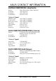
ASUS CONTACT INFORMATION ASUSTeK COMPUTER INC. (Asia-Pacific) Address: General Tel: General Fax: General Email: 150 Li-Te Road, Peitou, Taipei, Taiwan 112 +886-2-2894-3447 +886-2-2894-3449 info@asus.com.tw Technical Support MB/Others (Tel): Notebook (Tel): Desktop/Server (Tel): Support Fax: Support Email: Web Site: Newsgroup: +886-2-2890-7121 (English) +886-2-2890-7122 (English) +886-2-2890-7123 (English) +886-2-2890-7698 tsd@asus.com.tw www.asus.com.tw cscnews.asus.com.
CONTENTS 1. INTRODUCTION ............................................................................. 7 1.1 How This Manual Is Organized .................................................. 7 1.2 Item Checklist ............................................................................. 7 2. FEATURES ........................................................................................ 8 2.1 ASUS TR-DLS Motherboard ..................................................... 8 2.1.1 Specifications ..............
CONTENTS 4.3 Main Menu ................................................................................ 48 4.3.1 Primary & Secondary Master/Slave .............................. 49 4.3.2 Keyboard Features ......................................................... 52 4.4 Advanced Menu ........................................................................ 54 4.4.1 Chip Configuration ........................................................ 56 4.4.2 I/O Device Configuration .....................................
FCC & DOC COMPLIANCE Federal Communications Commission Statement This device complies with FCC Rules Part 15. Operation is subject to the following two conditions: • • This device may not cause harmful interference, and This device must accept any interference received, including interference that may cause undesired operation. This equipment has been tested and found to comply with the limits for a Class B digital device, pursuant to Part 15 of the FCC Rules.
1. INTRODUCTION How This Manual Is Organized 1. INTRODUCTION Manual / Checklist 1.1 This manual is divided into the following sections: 1. INTRODUCTION Manual information and checklist 2. FEATURES Production information and specifications 3. HARDWARE SETUP Instructions on setting up the motherboard. 4. BIOS SETUP Instructions on setting up the BIOS 5. SOFTWARE SETUP Instructions on setting up the included software 6. SOFTWARE REFERENCE Reference material for the included software 7.
2. FEATURES 2.1 ASUS TR-DLS Motherboard The ASUS TR-DLS motherboard is designed for server systems that require flexible configurations. Powered by dual Intel® Pentium® III Coppermine and Tualatin™ processors, the TR-DLS efficiently complies with today’s demand for a highintegration server. 2.1.1 Specifications 2. FEATURES Specifications 8 • Processor Support: Supports dual Socket 370-based Intel Pentium III Coppermine (256KB L2) and Tualatin (512KB L2) processors running up to 1.
• SMBus: Features the System Management Bus interface, which is used to physically transport commands and information between SMBus devices. • Wake-Up Support: Supports Wake-On-LAN and Wake-On-Ring, and BIOS Wake-Up. • LPC Server I/O: Provides two high-speed UART compatible serial ports and one parallel port with EPP and ECP capabilities. • Chassis Intrusion Detection: Chassis intrusion circuitry can log chassis open events into the system BIOS.
2. FEATURES 2.1.2 Performance UltraPerformance: Onboard Ultra160/320 (depending on model) dual channel SCSI controller with two connectors that support 30 Ultra160/320 SCSI devices in two channels. • Dual Speeds: CPU frequency can operate at either 133MHz or 100MHz depending on the CPU installed. • High-Speed Data Transfer Interface: SCSI transfers using Ultra160/320 (depending on model) dual channel SCSI controller can handle rates up to 160MB/s or 320MB/s.
2. FEATURES • Fan Status Monitoring and Alarm: To prevent system overheat and system damage, the CPU, power supply, and system fans can be monitored for RPM and failure. All the fans are set for its normal RPM range and alarm thresholds. • Temperature Monitoring and Alert: To prevent system overheat and system damage, this motherboard supports processor thermal sensing and auto-protection.
2. FEATURES 2.2 TR-DLS Motherboard Components See opposite page for locations. Location Processor Support (2) Socket 370 for Pentium® III Coppermine and Tualatin™ Processors ................................................................................. 2 2. FEATURES MB Components Chipsets ServerWorks® RCC Champion LE-T North Bridge ................. 4 ServerWorks® RCC Champion CSB5 South Bridge ................ 8 Low Pin Count (LPC) Super-I/O Chipset ..............................
2. FEATURES 2.2.1 Component Locations 1 2 3 4 5 2.
3. HARDWARE SETUP 3.1 TR-DLS Motherboard Layout 24.4cm (9.
3. HARDWARE SETUP Layout Contents Motherboard Settings 1) CLKSW p. 18 2) CONFIG p. 19 3) SCSIEN p. 21 4) VGAEN p. 21 5) KBPWR p. 22 6) CLRCMOS p. 22 Expansion Slots 1) DIMM 0/1/2/3 2) CPU 3) PCI1/2/3/4/5/6 p. 23 168-Pin System Memory Support p. 25 Central Processing Unit (CPU) p. 27 64-bit/32-bit PCI Bus Expansion Slot External Connectors 1) PS2KBMS p. 29 2) PS2KBMS p. 29 3) USB p. 29 4) RJ-45 p. 30 5) PRINTER p. 30 5) COM1/COM2 p. 30 6) VGA p.
3. HARDWARE SETUP 12) eRMC p. 37 ASUS Server Management Card Connector (50-pin) 13) IPMI p. 38 Intelligent Platform Management Interface (4-pin) 14) NIC (PANEL) p. 38 NIC Activity LED (2-pin) 15) STATUS (PANEL) p. 38 Status Activity LED (2-pin) 16) PWRSW (PANEL) p. 38 ATX Power Switch/Soft Off Lead (2-pin) 17) RESET (PANEL) p. 39 Reset Switch Lead (2-pin) 18) PWR.LED (PANEL) p. 39 System Power LED Lead (3-1 pin) 19) NMI (PANEL) p. 39 Non-Mask Interrupt Switch (2-pin) 20) SPEAKER (PANEL) p.
3. HARDWARE SETUP 3.3 Hardware Setup Procedure Complete the following steps before using your computer: 1. Check motherboard settings 2. Install memory modules 3. Install the Central Processing Unit (CPU) 4. Install a CPU terminator, if you installed only one CPU. 5. Install Expansion Cards 6. Connect ribbon cables, panel wires, and power supply cables 7. Configure the BIOS parameter settings 3.
3. HARDWARE SETUP 3.4 Motherboard Settings 3.4.1 Switches You may change the CPU core bus frequency multiple using the DIP switches. The white block on a DIP switch represents the ON or OFF position. The figure below shows the location of the DIP switches on the motherboard and the function of each switch. CLKSW ON ON OFF ON ON CONFIG TR-DLS DIP Switches 1 2 3 4 5 6 7 8 1 2 3 4 5 OFF TR-DLS 1. Frequency Selection 2. Frequency Selection 3. Frequency Selection 4. Frequency Selection 5.
3. HARDWARE SETUP 2. CPU Core Bus Frequency Multiple (Switches 5-8) These switches allow you to set the frequency multiple between the CPU internal and external frequencies. Set these switches in conjunction with the settings of the CLKSW switches. 8.0x ON 1 2 3 4 5 6 7 8 1 2 3 4 5 6 7 8 1 2 3 4 5 6 7 8 1 2 3 4 5 6 7 8 5.5x 7.5x 1 2 3 4 5 6 7 8 ON 7.0x ON 1 2 3 4 5 6 7 8 ON ON 5.0x 3.5x ON 1 2 3 4 5 6 7 8 ON 1 2 3 4 5 6 7 8 1 2 3 4 5 6 7 8 1 2 3 4 5 6 7 8 6.5x ON 6.0x 3.0x 4.
3. HARDWARE SETUP 1 2 3 4 5 6 7 8 ON ON 1 2 3 4 5 6 7 8 1 2 3 4 5 6 7 8 10.5x 12.0x 1 2 3 4 5 6 7 8 1 2 3 4 5 6 7 8 ON ON ON 1 2 3 4 5 6 7 8 1 2 3 4 5 6 7 8 1 2 3 4 5 6 7 8 ON 1 2 3 4 5 6 7 8 11.5x 11.0x 8.5x 10.0x ON 1 2 3 4 5 6 7 8 ON 1 2 3 4 5 6 7 8 9.5x 1 2 3 4 5 6 7 8 ON ON 8.0x 7.5x 9.0x ON 1 2 3 4 5 6 7 8 ON 1 2 3 4 5 6 7 8 ON 3. H/W SETUP Motherboard Settings TR-DLS CPU (Tualatin) Frequency Multiple Selection ON 7.0x 6.5x 6.0x 5.5x 4.
3. HARDWARE SETUP 3.4.2 Jumpers The jumpers on the motherboard allow you to change some feature settings to suit your customized system configuration. IMPORTANT! Before changing any jumper setting, make sure to read the jumper descriptions and setting requirements in this section. 3. H/W SETUP Motherboard Settings 1. SCSI Settings (3-pin SCSIEN) This jumper allows you to enable or disable the onboard SCSI function. Set to Enable (pins 1-2) if you wish to use SCSI devices.
3. HARDWARE SETUP 3. Keyboard Power Settings (3-pin KBPWR) This jumper allows you to enable or disable the keyboard wake-up feature. Set this jumper to pins 2-3 (5VSB) if you wish to wake up the computer when you press a key on the keyboard. This feature requires an ATX power supply that can supply at least 1A on the +5VSB lead, and a corresponding setting in the BIOS (see section 4.5.1 Power Up Control). TR-DLS KBPWR 2 1 5V (Default) 3 2 5VSB 3.
3. HARDWARE SETUP 3.5 System Memory This motherboard uses only Dual Inline Memory Modules (DIMMs). Four DIMM sockets are available for 3.3Volt (power level) registered Synchronous Dynamic Random Access Memory (SDRAM) of 16MB, 32MB, 64MB, 128MB, 256MB, 512MB, or 1GB densities with Serial Presence Detect (SPD) and Error Check and Correction (ECC). The motherboard supports a memory configuration of up to 4GB. One side (with memory chips) of the DIMM takes up one row on the motherboard. 3.5.
3. HARDWARE SETUP 3.5.2 Memory Installation WARNING! Make sure that you unplug the power supply when adding or removing memory modules or other system components. Failure to do so may cause severe damage to both the motherboard and expansion cards (see 3.3 Hardware Setup Procedure for more information). Insert a DIMM into the DIMM socket as shown. Because the number of pins are different on either side of the breaks, the module only fits in one direction.
3. HARDWARE SETUP 3.6 Central Processing Unit (CPU) The motherboard comes with a dual Socket 370 for Intel Pentium III Coppermine (256KB L2) and Tualatin (512KB L2) CPUs running up to 1.53+GHz with 100/ 133MHz Front Side Bus (FSB). The following illustration shows the location of the CPU sockets on the motherboard and the correct CPU and terminator orientation. Pentium III (Coppermine) FC-PGA Gold Arrow Pentium III (Tualatin) 3.
3. HARDWARE SETUP 3.6.1 Installing the CPU and Terminator Follow these steps to install a CPU. 1. Locate the ZIF socket on the motherboard. 2. Unlock the socket by pressing the lever sideways then lifting it up to a 90°-100° angle. 3. H/W SETUP CPU Installation 3. Position the CPU above the socket such that its notched or marked corner matches the socket corner near the end of the lever, while making sure that the CPU is parallel to the socket. 4.
3. HARDWARE SETUP 3.7 Expansion Cards WARNING! Unplug the power supply when adding or removing expansion cards or other system components. Failure to do so may cause severe damage to both your motherboard and expansion cards. 3.7.1 Expansion Card Installation Procedure 3. H/W SETUP Expansion Cards 1. Read the documentation for your expansion card and make any necessary hardware or software settings for your expansion card, such as jumpers. 2.
3. HARDWARE SETUP 3.7.2 Assigning IRQs for Expansion Cards Some expansion cards need an IRQ to operate. Generally, an IRQ must be exclusively assigned to one use. In a standard design, there are 16 IRQs available but most of them are already in use, leaving 6 IRQs free for expansion cards. If the motherboard has PCI audio onboard, an additional IRQ will be used. If the motherboard also has MIDI enabled, another IRQ will be used, leaving 4 IRQs free.
3. HARDWARE SETUP 3.8 Connectors 3.8.1 External Connectors 1) PS/2 Mouse Port (Green 6-pin PS2KBMS) The system will direct IRQ12 to the PS/2 mouse if one is detected. If one is not detected, expansion cards can use IRQ12. 3. H/W SETUP Connectors PS/2 Mouse (6-pin female) 2) PS/2 Keyboard Port (Purple 6-pin PS2KBMS) This connection is for a standard keyboard using an PS/2 plug (mini DIN). This connector does not allow standard AT size (large DIN) keyboard plugs.
3. HARDWARE SETUP 4) Fast Ethernet LAN Port (RJ-45) The RJ-45 connector allows connection to a Local Area Network (LAN) through a network hub. RJ45 5) Parallel Port (Burgundy 25-pin PRINTER) A 25-pin port is available for a parallel printer. Enable the parallel port and select the IRQ through Onboard Parallel Port parameter in BIOS. (See 4.4.2 I/O Device Configuration). Parallel (Printer) Port (25-pin female) 3.
3. HARDWARE SETUP 3.8.2 Internal Connectors WARNING! Some pins are used for connectors or power sources. These are clearly distinguished from jumpers in the Motherboard Layout. Placing jumper caps over these connector pins will cause damage to your motherboard. IMPORTANT: Always connect ribbon cables such that the red stripe matches Pin 1 on the connector. Pin 1 is usually on the side closest to the power connector on hard disk drives and CD-ROM drives, but may be on the opposite side on floppy disk drives.
3. HARDWARE SETUP 2) IDE/SCSI Activity LED (2-pin HDLED) This connector supplies power to the chassis activity LED. Read and write activity by devices connected to the primary/secondary IDE and SCSI connectors cause the LED to light up. TR-DLS TIP: If the case-mounted LED does not light, try reversing the 2-pin plug. HD_LED + TR-DLS HD Activity LED 3. H/W SETUP Connectors 3) Floppy Disk Drive Connector (34-1 pin FLOPPY) This connector supports the provided floppy drive ribbon cable.
3. HARDWARE SETUP 4) Wake-On-LAN Connector (3-pin WOL_CON) This connector supports a LAN card with a Wake-On-LAN output. The connector powers up the system when a wakeup packet or signal is received through the LAN card. IMPORTANT: This feature requires that the BIOS item Onboard LAN Power Up is enabled (see 4.5.1 Power Up Control) and that your system has an ATX power supply with at least 720mA +5V standby power.
3. HARDWARE SETUP 6) Two 68-pin Ultra160/320 SCSI Connectors (SCSI-A, SCSI-B) This motherboard has two 68-Pin Ultra160/320 SCSI connectors; one for each of the two channels. Each channel can support a maximum of 15 devices as specified by Ultra160 standards. SCSI-A 68-Pin Ultra160/ Ultra2-Wide SCSI Connector 1 35 TR-DLS 34 68 1 35 SCSI-B 68-Pin Ultra160/ Ultra2-Wide SCSI Connector 34 68 TR-DLS Onboard SCSI Connectors 3.
3. HARDWARE SETUP 7) CPU and Chassis Fan Connectors (3-pin CPU_FAN1/2, CHA_FAN1/2) These connectors support cooling fans of 860mA (10.3 Watts) or less. Orient the fans so that the heat sink fins allow airflow to go across the onboard heat sink(s) instead of the expansion slots. Depending on the fan manufacturer, the wiring and plug may be different. The red wire should be positive, while the black should be ground. Connect the fan’s plug to the board taking into consideration the polarity of the connector.
3. HARDWARE SETUP 9) SMBus Connector (6-1 pin SMB, BPSMB) These connectors allow you to connect SMBus (System Management Bus) devices. SMBus devices communicate by means of the SMBus with an SMBus host and/or other SMBus devices. SMBus is a specific implementation of an I2C bus, which is a multi-device bus; that is, multiple chips can be connected to the same bus and each one can act as a master by initiating data transfer. The BPSMB connector is for a backplane board that supports an SMBus interface.
3. HARDWARE SETUP 11) ATX Power Connector (20/24-pin block ATXPWR) This connector is for an ATX power supply with 20/24-pin power connector. The connector from the power supply is designed to fit this connector in only one orientation. Find the proper orientation and push down firmly until the plug completely fits in. IMPORTANT: Make sure that your ATX power supply can supply at least 720mA on the +5-volt standby lead (+5VSB).
3. HARDWARE SETUP 13) IPMI Connector (4-pin ) This connector allows you to connect devices that support Intelligent Platform Manangement Interface (IPMI) Rev1.0 or Rev1.5. IPMIDATA GND IPMICLK NC TR-DLS TR-DLS IPMI Connector Power LED + NIC activity LED– Power LED – Keylock GND NMI button +5V HDD access LED+ HDD access LED– Speaker TR-DLS 1 10 RESET button GND 20 Power Switch GND 11 NIC activity LED+ Status LED+ Status LED – 3.
• Reset Switch Lead (2-pin) This 2-pin connector connects to the case-mounted reset switch for rebooting your computer without having to turn off your power switch. This is a preferred method of rebooting to prolong the life of the system power supply. • System Power LED Lead (3-1 pin) This 3-1 pin connector connects to the system power LED that lights up when the system is powered on and blinks when it is in sleep or soft-off mode. This feature can be programmed through the ASUS ASIC.
3. HARDWARE SETUP 3.9 Starting Up the First Time 1. 2. 3. 4. 5. 3. H/W SETUP Connectors Starting Up After making all the connections, replace the system case cover. Be sure that all switches are off (in some systems, marked with ). Connect the power cord to the power connector at the back of the system chassis. Connect the power cord to a power outlet that is equipped with a surge protector. Turn on the devices in the following order: a. Monitor b.
4. BIOS SETUP 4.1 Managing and Updating Your BIOS 4.1.1 Upon First Use of the Computer System It is recommended that you save a copy of the original motherboard BIOS along with a Flash Memory Writer utility (AFLASH.EXE) to a bootable floppy disk in case you need to reinstall the BIOS later. AFLASH.EXE is a Flash Memory Writer utility that updates the BIOS by uploading a new BIOS file to the programmable flash ROM on the motherboard. This file works only in DOS mode.
4. BIOS SETUP 5. Select 1. Save Current BIOS to File from the Main menu and press . The Save Current BIOS To File screen appears. 6. Type a filename and the path, for example, A:\XXX-XX.XXX and then press . 4.
4. BIOS SETUP 4.1.2 Updating BIOS Procedures WARNING! Update the BIOS only if you have problems with the motherboard and you know that the new BIOS revision will solve your problems. Careless updating can result to more problems with the motherboard! 4. BIOS SETUP Updating BIOS 1. Download an updated ASUS BIOS file from the Internet (WWW or FTP) (see ASUS CONTACT INFORMATION on page 3 for details) and save to the boot floppy disk you created earlier. 2. Boot from the floppy disk. 3.
4. BIOS SETUP 7. The utility starts to program the new BIOS information into the Flash ROM. The boot block is updated automatically only when necessary. This minimizes the possibilities of boot problems in case of update failures. When the programming is done, Flashed Successfully appears. 8. Follow the onscreen instructions to continue. 4. BIOS SETUP Updating BIOS WARNING! If you encounter problems while updating the new BIOS, DO NOT turn off the system because this may cause boot problems.
4. BIOS SETUP 4.2 BIOS Setup Program This motherboard supports a programmable EEPROM that you can update using the provided utility described in 4.1 Managing and Updating Your BIOS. The utility is used if you are installing a motherboard, reconfiguring your system, or prompted to “Run Setup”. This section describes how to configure your system using this utility. Even if you are not prompted to use the Setup program, at some time in the future you may want to change the configuration of your computer.
4. BIOS SETUP 4.2.1 BIOS Menu Bar The top of the screen has a menu bar with the following selections: MAIN Use this menu to make changes to the basic system configuration. ADVANCED Use this menu to enable and make changes to the advanced features. POWER Use this menu to configure and enable Power Management features. BOOT Use this menu to configure the default system device used to locate and load the Operating System. EXIT Use this menu to exit the current menu or specify how to exit the Setup program.
4. BIOS SETUP General Help In addition to the Item Specific Help window, the BIOS setup program also provides a General Help screen. You may launch this screen from any menu by simply pressing or the + combination. The General Help screen lists the legend keys with their corresponding functions. Saving Changes and Exiting the Setup Program See 4.7 Exit Menu for detailed information on saving changes and exiting the setup program.
4. BIOS SETUP 4.3 Main Menu When the Setup program is accessed, the following screen appears: 4. BIOS SETUP Main Menu System Time [XX:XX:XX] Sets your system to the time that you specify (usually the current time). The format is hour, minute, second. Valid values for hour, minute and second are Hour: (00 to 23), Minute: (00 to 59), Second: (00 to 59). Use the or + keys to move between the hour, minute, and second fields.
4. BIOS SETUP 4.3.1 Primary & Secondary Master/Slave 4. BIOS SETUP Master/Slave Devices Type [Auto] Select [Auto] to automatically detect an IDE hard disk drive. If automatic detection is successful, Setup automatically fills in the correct values for the remaining fields on this sub-menu. If automatic detection fails, this may be because the hard disk drive is too old or too new. If the hard disk was already formatted on an older system, Setup may detect incorrect parameters.
4. BIOS SETUP [User Type HDD] Manually enter the number of cylinders, heads and sectors per track for the drive. Refer to the drive documentation or on the drive label for this information. 4. BIOS SETUP Master/Slave Devices NOTE: After entering the IDE hard disk drive information into BIOS, use a disk utility, such as FDISK, to partition and format new IDE hard disk drives. This is necessary so that you can write or read data from the hard disk.
4. BIOS SETUP Translation Method [LBA] Select the hard disk drive type in this field. When Logical Block Addressing (LBA) is enabled, the 28-bit addressing of the hard drive is used without regard for cylinders, heads, or sectors. Note that LBA Mode is necessary for drives with more than 504MB storage capacity. Configuration options: [LBA] [LARGE] [Normal] [Match Partition Table] [Manual] Cylinders This field configures the number of cylinders.
4. BIOS SETUP PIO Mode [4] This option lets you set a PIO (Programmed Input/Output) mode for the IDE device. Modes 0 through 4 provide successive increase in performance. Configuration options: [0] [1] [2] [3] [4] Ultra DMA Mode [Disabled] Ultra DMA capability allows improved transfer speeds and data integrity for compatible IDE devices. Set to [Disabled] to suppress Ultra DMA capability. To make changes to this field, set the Type field to [User Type HDD].
4. BIOS SETUP Hotkey to Lock Keyboard [Disabled] This field allows you to activate the OS independent keyboard lock function using selected hot keys. You must set a user password or a supervisor password before enabling the keyboard lock feature. Configuration options: [Ctrl-Alt A] [Ctrl-Alt Z] [Ctrl-Alt X] [ Ctrl-Shft A] [Ctrl-Shft Z] [Ctrl-Shft X] [Disabled] Keyboard Idle Timer [Disabled] This field allows you to activate the OS independent keyboard lock function using selected hot keys.
4. BIOS SETUP Halt On [All Errors] This field specifies the types of errors that will cause the system to halt. Configuration options: [All Errors] [No Error] [All but Keyboard] [All but Disk] [All but Disk/ Keyboard] Installed Memory [XXX MB] This field automatically displays the amount of conventional memory detected by the system during the boot process. 4.4 Advanced Menu 4. BIOS SETUP Advanced Menu CPU Speed This parameter displays the auto-detected CPU speed.
4. BIOS SETUP BIOS Update [Enabled] This functions as an update loader integrated into the BIOS to supply the processor with the required data. In the default position of [Enabled], the BIOS will load the update on all processors during system bootup. Configuration options: [Disabled] [Enabled] PS/2 Mouse Function Control [Auto] The default of [Auto] allows the system to detect a PS/2 mouse on startup. If detected, IRQ12 will be used for the PS/2 mouse.
4. BIOS SETUP 4.4.1 Chip Configuration 4. BIOS SETUP Chip Configuration Video Memory Cache Mode [UC] USWC (uncacheable, speculative write combining) is a new cache technology for the video memory of the processor. It can greatly improve the display speed by caching the display data. You must set this to UC (uncacheable) if your display card cannot support this feature; otherwise your system may not boot.
4. BIOS SETUP 4.4.2 I/O Device Configuration Floppy Disk Access Control [R/W] When set to [Read Only], this field protects files from being copied to floppy disks by allowing reads from the floppy disk drive but not writes. The setup default [R/W] allows both reads and writes. Configuration options: [R/W] [Read Only] 4. BIOS SETUP I/O Device Config Onboard Serial Port 1 [3F8H/IRQ4] Onboard Serial Port 2 [2F8H/IRQ3] These fields allow you to set the addresses for the onboard serial connectors.
4. BIOS SETUP ECP DMA Select [3] This field allows you to configure the parallel port DMA channel for the selected ECP mode. This selection is available only if you select [ECP] or [ECP+EPP] in Parallel Port Mode above. Configuration options: [1] [3] 4.4.3 PCI Configuration 4. BIOS SETUP PCI Configuration Slot 1, Slot 2, Slot 3, Slot 4, Slot 5, Slot 6 IRQ [Auto] These fields set how IRQ use is determined for each PCI slot.
4. BIOS SETUP Onboard SCSI BIOS [Auto] [Auto] allows the motherboard’s BIOS to detect whether you have a Symbios SCSI controller. If the Symbios SCSI controller is detected, the motherboard’s Symbios BIOS will be enabled; if no Symbios SCSI controller is detected, the onboard Symbios SCSI BIOS will be disabled. Setting to [Disabled] disactivates the SYMBIOS SCSI BIOS onboard so that the BIOS on an add-on SYMBIOS SCSI card can be used.
4. BIOS SETUP 4.5 Power Menu The Power menu allows you to reduce power consumption. This feature turns off the video display and shuts down the hard disk after a period of inactivity. 4. BIOS SETUP Shadow Configuration Power Management [User Defined] This option must be enabled to use any of the automatic power saving features. If this menu item is set to [Disabled], power management features will not function regardless of other field settings on this menu.
4. BIOS SETUP Video Off Option [Suspend -> Off ] This field determines when to activate the video off feature for monitor power management. Configuration options: [Always On] [Suspend -> Off] Video Off Method [DPMS OFF] This field defines the video off features. The DPMS (Display Power Management System) feature allows the BIOS to control the video display card if it supports the DPMS feature. [Blank Screen] only blanks the screen (use this for monitors without power management or “green” features.
4. BIOS SETUP 4.5.1 Power Up Control AC PWR Loss Restart [Disabled] This allows you to set whether you want your system to reboot after the power has been interrupted. [Disabled] leaves your system off. [Previous State] reverts your system to the same state before the power interruption. Configuration options: [Disabled] [Previous State] 4.
4. BIOS SETUP 4. BIOS SETUP Power Up Control Automatic Power Up [Disabled] This allows an unattended or automatic system power up. You may configure your system to power up at a certain time of the day by selecting [Everyday] or at a certain time and day by selecting [By Date]. NOTE: Automatic Power Up will not work if the system is powered down by operating systems, such as Windows 98, which have ACPI support enabled.
4. BIOS SETUP 4.5.2 Hardware Monitor 4. BIOS SETUP Power Up Control MB Temperature [xxxC/xxxF] CPU1 Temperature [xxxC/xxxF] CPU2 Temperature [xxxC/xxxF] The onboard hardware monitor is able to detect the MB (motherboard) and CPU temperatures. Set to [Ignore] only if necessary. CPU1 Fan Speed [xxxxRPM] CPU2 Fan Speed [xxxxRPM] Chassis1 Fan Speed [xxxxRPM] Chassis2 Fan Speed [xxxxRPM] The onboard hardware monitor is able to detect the CPU fan speed and the chassis fan speed in rotations per minute (RPM).
4. BIOS SETUP 4.6 Boot Menu Boot Sequence 4. BIOS SETUP Hardware Monitor The Boot menu allows you to select among the four possible types of boot devices listed using the up and down arrow keys. By using the <+> or key, you can promote devices and by using the <-> key, you can demote devices. Promotion or demotion of devices alters the priority which the system uses to search for a boot device on system power up.
4. BIOS SETUP Plug & Play O/S [No] This field allows you to use a Plug-and-Play (PnP) operating system to configure the PCI bus slots instead of using the BIOS. When [Yes] is selected, interrupts may be reassigned by the OS. When a non-PnP OS is installed or you want to prevent reassigning of interrupt settings, select the default setting of [No]. Configuration options: [No] [Yes] MPS 1.4 Support [Enabled] This field allows you to enable or disable the MultiProcessor Specification 1.4 support.
4. BIOS SETUP 4.7 Server Menu 4. BIOS SETUP Boot Menu Remote Console [Disabled] This field allows the text mode VGA display to be sent out to VT100 terminal through COM1. This function is effective at BIOS POST and DOS environment. Configuration options: [Disabled] [Enabled] [POST Only] Side0/1 of DIMM0, Side0/1 of DIMM1, Side0/1 of DIMM2, Side0/1 of DIMM3 [Enabled] These memory isolation fields allow you to disable specific rows of installed registered DIMMs.
4. BIOS SETUP 4.8 Exit Menu Once you have made all of your selections from the various menus in the Setup program, you should save your changes and exit Setup. Select Exit from the menu bar to display the following menu: 4. BIOS SETUP Exit Menu NOTE: Pressing does not exit this menu. You must select one of the options from this menu or from the legend bar to exit this menu.
4. BIOS SETUP Load Setup Defaults This option allows you to load the default values for each of the parameters on the Setup menus. When this option is selected or if is pressed, a confirmation is requested. Select [Yes] to load default values. You can now select Exit Saving Changes or make other changes before saving the values to the non-volatile RAM. Discard Changes This option allows you to discard the selections you made and restore the values you previously saved.
4. BIOS SETUP 4.
® TR-DLS Dual Socket 370 Motherboard 5.
Contents 5.1 5.2 5.3 5.4 5. Driver Installation Table of Contents 5.5 72 Microsoft Windows NT Server 4.0 ...................................... 75 I. LSI SCSI Driver Installation ............................................ 75 A. Preparing a LSI Driver Diskette .............................. 75 B. New System Installation .......................................... 75 C. Existing System Installation .................................... 77 II. Intel 82550 Network Driver Installation .....................
Contents 5.7 5.8 5. Driver Installation Table of Contents 5.6 II. Intel 82550 Network Driver Installation .......................... 95 III. ATI Rage XL Display Driver Installation ........................ 95 SCO Open Server 5.0.x ........................................................ 96 I. LSI SCSI Driver Installation ............................................ 96 A. Building the SCO OpenServer BTLD Diskette ....... 96 B. New System Installation .......................................... 97 C.
ASUS TR-DLS User’s Manual
5. OS Driver Installation 5.1 I. Microsoft Windows NT Server 4.0 LSI SCSI Driver Installation Windows NT 4.0 do not have drivers for such new SCSI controllers, the user must load the driver manually prior to Windows NT 4.0 installation. A. Preparing a LSI Driver Diskette The drivers are located on the ASUS Driver Support CD at: \Drivers\Sdms\Drivers\WINNT Copy all the files and subdirectory under the WINNT subdirectory to the root directory of a clean floppy diskette.
5. OS Driver Installation NOTE: If F6 is not pressed, the user is still given the opportunity to load additional drivers later in the installation process. However, any drivers loaded during Windows NT Setup are not immediately recognized and no devices controlled by that driver are available during Windows NT Setup. 3.
5. OS Driver Installation 8. When prompted for the manufacturer-supplied hardware support disk, insert the appropriate LSI driver diskette containing the Windows NT driver required to support your LSI adapter(s) and press Enter. The driver files are distributed with ASUS Driver Support CD and are created from the previous section for “Preparing a LSI Driver Diskette”. 9. Depending on the driver being installed, Symbios Ultra3 PCI SCSI Driver is shown highlighted. Press Enter to proceed. 10.
5. OS Driver Installation 9. For the path to the OEM SCSI Adapter files, A:\WINNT\MINIPORT should be displayed. Select Continue. Then remove the floppy diskette from your A: drive. 10. The System Settings Change message displays: “You must restart your computer before the new settings take effect. Do you want to restart your computer now?” Click on the Yes button to restart and reboot Windows NT. If you choose Cancel, remember that you must restart before the new driver loads. 11.
5. OS Driver Installation C. Existing System Installation Double-click the Network icon in the Control Panel. 2. Select the Adapter tab. 3. Click Add. You’ll see a list of adapters. 4. Don’t select an adapter from this list. Instead, insert the Intel PRO/100+ Adapter diskette and click Have Disk. 5. Type A:\ (for floppy) in the dialog box and click OK. Then follow the prompts to complete installation. When the adapter is added you’ll see a new adapter listed in the Network adapters list. 6.
5. OS Driver Installation III. ATI Rage XL Display Driver Installation 1. Start up Windows NT in VGA mode. 2. Run the Windows NT Display program located in the Control Panel, under Settings in the Start menu or right click the mouse button on the desktop and select Properties from the popup menu. 3. Select the Settings tab. 4. Select Display Type.... 5. Select Change... from the display options. 6. Select Have Disk... 7.
5. OS Driver Installation 5.2 I. Microsoft Windows 2000 Server LSI SCSI Driver Installation User only need to load the driver manually when the TR-DLS M/B has build-in with LSI SYM53C1010 SCSI controller. A. Preparing a Symbios Driver Diskette The drivers are located on ASUS Driver Support CD at: \Drivers\Sdms\Drivers\Win2k Copy all the files and subdirectory under the Win2k subdirectory to the root directory of a clean floppy diskette. Use this LSI driver diskette during installation.
5. OS Driver Installation 5. The appropriate driver is shown highlighted. Press Enter to proceed. 6. Return to the Windows 2000 Setup screen. Press Enter to proceed. The message about setup loading files appears. At this point, simply follow the Microsoft Windows 2000 installation procedure. C. Existing System Installation 5. Driver Installation Win2000 Server 82 1. Boot Windows 2000 and log on as Administrator. 2. Right click on My Computer and click on Properties. 3.
5. OS Driver Installation 10. A list of suitable drivers appears. The entry for the upgrade driver can be verified by scrolling the display to the right, and viewing the Location field. Highlight the driver for the upgrade installation disk and click on the Next button. 11. In some cases, a message will state that this driver is not digitally signed. This message informs the user that a non-signed driver is being installed.
5. OS Driver Installation II. Intel 82550 Network Driver Installation The Windows 2000 system can recognize onboard Intel LAN chip as Intel 8255x-based PCI Ethernet Adapter [10/100] . Basically, user doesn t need to load/change any driver for onboard LAN device. However, you can change the bundled network driver on Windows 2000 by following approach. A. Preparing Intel 82550 Lan Driver Diskette If you need to use a floppy disk to install the on-board Intel 82550 network adapter drivers, use the MAKEDISK.
5. OS Driver Installation 7. Select “Network adapters” in Hardware Type and Click Next. 8. Click Have Disk…. Select A: floppy diskette for the network driver and click OK. 9. Select “Intel® PRO/100 S PCI Adapter” from the listed Network Adapters. Click Next. System would prompt you an Update Driver Warning message. Click Yes to continue installing driver. 10. Click Finish. Windows 2000 system will prompt if you want to restart the system now.
5. OS Driver Installation 5.3 Microsoft Windows XP Professional Windows XP contains default driver to support Intel 82550 chipset, ATI Rage XL chipset, and LSI 53C1010R SCSI chipset. NOTE: For Windows XP Professional users, we recommended that you use the Intel 82550 driver from the TR-DLS support CD. 5.4 I. Novell NetWare Server LSI SCSI Driver Installation A single driver (*HAM) is provided for the Novell NetWare 4.XX, and 5.X environments.
5. OS Driver Installation 1. Begin the file server installation according to the instructions in the file server installation chapter in the Novell NetWare Installation Manual. 2. When the NetWare installation procedure prompts you a Device type screen, press Modify to add a Storage adapters: (Default only IDEATA available). Press INS for adding a new driver. Please put the LSI driver for NetWare diskette into drive A: Then use the INS key to select an unlisted driver. A dialog box appears.
5. OS Driver Installation 3. Highlight Disk and CD-ROM Drivers (e.g., IDEATA). Press Enter and load an additional driver. Then press the INS key. The system always defaults to the A: path. Highlight the HAM driver and press Enter. Select Yes to save and move the driver into the operating system. Press Enter, the system will start to copy the files. 4. Load a separate instance of the driver for every LSI SCSI controller channel or host adapter present in the system.
5. OS Driver Installation where [operating system] is the OS for which you are creating the diskette, and [destination] is the drive letter and path (such as A:). If no destination is specified, the A: drive will be used. The possible [operating system] options are: NT = Microsoft Windows NT W2K = Microsoft Windows* 2000 NW = Novell NetWare servers and clients Make sure you have a 1.44 MB formatted, non-bootable diskette in the floppy drive when using this utility. B. NetWare 4.XX and 5.X Installations 1.
5. OS Driver Installation NET=xxxxxxxx is the unique network address for that LAN segment. The default frame type is 802.2. If your workstation needs to use the 802.3 frame type, see the section later in this document about using multiple frame types on one adapter. III. ATI Rage XL Display Driver Installation User can select the “Super VGA” for the X Server on NetWare 5.x server system. The other NetWare system didn’t support X Server and user didn’t need the VGA driver support. 5.5 I.
5. OS Driver Installation The is where the dd image is located. On this CD-ROM, the dd image file is located here: \Drivers\Sdms\Drivers\UNIXES\SOLARIS\Solaris7\SYMITU.DD For DOS System Users: Under this section, DOS system users have two choices. 1. Use a utility that will copy the raw dd image onto a 1.44 Mbytes floppy diskette. This dd image is located at: \Drivers\Sdms\Drivers\UNIXES\SOLARIS\Solaris7\SYMITU.DD RAWRITE3.
5. OS Driver Installation 3. Remove the Solaris Device Configuration Assistant Diskette from the diskette drive and insert the first Solaris Driver ITU diskette you want. 4. Press F2_Continue. The Select Solaris System Version screen appears. 5. Select the appropriate Solaris operating system, and press F2_Continue. The Loading Driver Update Software screen appears, along with a progress bar that shows the percentage of drivers that have been extracted from the diskette.
5. OS Driver Installation 13. At the Boot Solaris screen, select the device controller attached to the device that contains your install medium, i.e., CD-ROM or Network device. 14. Press F2_Continue. Drivers for the device controller that you selected are displayed. Your system boots to run the install program. The install program starts and your machine begins booting the complete Solaris operating environment.
5. OS Driver Installation C. Existing System Installation Before adding new or updated drivers, the newly supported hardware devices should be installed and configured according to the instructions in the corresponding Device Reference Page, if any. See the Device Reference Manual for Solaris (Intel Platform Edition). When the Solaris Intel Platform Edition software is already installed, the simplest way to add new or updated drivers is to install the Driver ITU diskettes as patches on your system.
5. OS Driver Installation 7. If the driver is the one that you want to install, type Y for yes or press Enter. If the driver is not the one you want to install, type N for no. If you specify yes, the install.sh script installs the driver you indicated as well as bootmod and bootbin patches. 8. When the installation has completed, and the install.sh script exits, un-mount the diskette by typing at the command prompt: # cd / # umount /mnt 9. Remove the Solaris Driver ITU diskette from the diskette drive.
5. OS Driver Installation 5.6 I. SCO Open Server 5.0.x LSI SCSI Driver Installation A. Building the SCO OpenServer BTLD Diskette To create a BTLD diskette for SCO OpenServer system, copy the raw dd image file onto a 1.44 Mbytes floppy diskette. This process is dependent upon the operating system that you are using to create this diskette. See the instructions below for UNIX System and DOS System Users. For UNIX System Users: Follow these steps to create the BTLD diskette: 1. Insert a 3.
5. OS Driver Installation B. New System Installation This procedure installs SCO UNIX onto a hard disk drive. This installation is necessary to build a new UNIX kernel that includes your SDMS driver. During installation, you are given the option of retaining current partitions on the root hard disk. For instance, you could have a DOS partition or a user UNIX partition already established on the drive. For more details on UNIX installation, refer to the SCO OpenServer Handbook. 1.
5. OS Driver Installation C. Existing System Installation This procedure assumes SCO UNIX is already installed on a hard disk drive. This installation is necessary to build a new UNIX kernel that includes the proper LSI host adapter driver. The basic steps for accomplishing this are outlined below. For more details on UNIX installation, refer to the SCO UNIX System Administrator’s Reference Manual. 1. The SCO OpenServer 5 system automatically creates a file unix.safe during installation.
5. OS Driver Installation b. “Do you want the kernel environment rebuilt (y/n)?” Type: y Press Enter. 9. To activate the new kernel, you must reboot the system. At the command prompt, type: # reboot (or init 6) II. Intel 82550 Network Driver Installation SCO OpenServer 5.0.6 system can correctly recognize Intel 82550 network controller during installation. User doesn’t need to load or modify the network driver for the onboard LAN device.
5. OS Driver Installation III. ATI Rage XL Display Driver Installation SCO OpenServer 5.0.6 system can correctly recognize ATI Rage XL graphic controller (ATI MACH64) during installation. User doesn’t need to load or modify the video driver for the onboard VGA device. 5.7 I. SCO UnixWare Server LSI SCSI Driver Installation A. Building the SCO UnixWare C8XX BTLD Diskette To create a C8XX BTLD diskette to use with UnixWare 2.1.X or UnixWare 7, copy the raw dd image file onto a 1.
5. OS Driver Installation For DOS System Users: Under this section, DOS system users have two choices. 1. Use a utility that will copy the raw dd image onto a 1.44 Mbytes floppy diskette. For UnixWare 2.1.X, this dd image is located at: \Drivers\Sdms\Drivers\UNIXES\UNIXWARE\UW21X\UNIXWARE.DD For UnixWare 7, this dd image is located at: \Drivers\Sdms\Drivers\UNIXES\UNIXWARE\UW7 \UNIXWARE.DD RAWRITE3.
5. OS Driver Installation C. Existing System Installation Adding or Updating the C8XX Package for LSI SCSI controller. Before you install the C8XX driver, make a backup copy of the existing kernel: 1. Log on as root. 2. At the shell prompt, type: # cp /stand/unix /stand/unix.safe Use this copy of the old kernel to reboot the system if the driver installation fails. Refer to Troubleshooting for more information. 3. Once the old kernel is saved, insert the “PCI SCSI SCO UnixWare driver” diskette. 4.
5. OS Driver Installation II. Intel 82550 Network Driver Installation SCO UnixWare 7.1.1 system can correctly recognize Intel 82550 network controller during installation. User doesn’t need to load or modify the network driver for the onboard LAN device. User also can find the Intel 82550 Network driver from ASUS Driver Support CD at: \Drivers\Lan\UNIX\UW7DDI8 It is not necessary, nor recommended, to remove previous versions of this package from the system before installing this updated version.
5. OS Driver Installation 5.8 I. Linux RedHat 7.x LSI SCSI Driver Installation The SYM53C1010 controller, user must need to load the LSI driver (RedHat 7.0) for support the SYM53C1010 controller. The RedHat 7.1 or later version already bundle with SYM53C1010 driver support. As for Supporting RedHat 7.0, Please downloads the LSI 1010 driver “redhat70.exe” for RedHat 7.0 from ASUS Web site at http://www.asus.com.tw/products/addon/ scsi/scsilan_drv.html.