
User's Manual

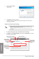


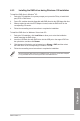
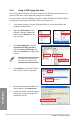


Table Of Contents
- Safety information
- About this guide
- P8H77-V specifications summary
- Chapter 1: Product introduction
- Chapter 2: Hardware information
- 2.1 Before you proceed
- 2.2 Motherboard overview
- 2.3 Building your computer system
- 2.3.1 Additional tools and components to build a PC system
- 2.3.2 CPU installation
- 2.3.3 CPU heatsink and fan assembly installation
- 2.3.4 DIMM installation
- 2.3.5 Motherboard installation
- 2.3.6 ATX Power connection
- 2.3.7 SATA device connection
- 2.3.8 Front I/O Connector
- 2.3.9 Expension Card installation
- 2.3.10 Rear panel connection
- 2.3.11 Audio I/O connections
- 2.4 Starting up for the first time
- 2.5 Turning off the computer
- Chapter 3: BIOS setup
- Chapter 4: Software support
- Chapter 5: Multiple GPU technology support
- Appendices
- http://csr.asus.com/english/Takeback.htm
5-2
Chapter 5: Multiple GPU technology support
Chapter 5
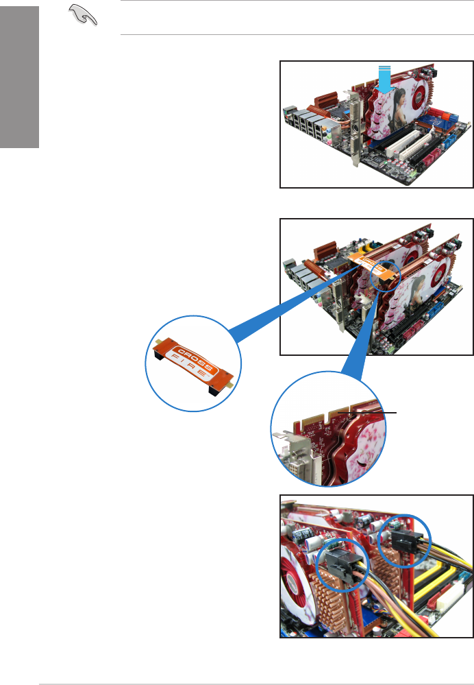
5. Connect two independent auxiliary power
sources from the power supply to the two
graphics cards separately.
6. Connect a VGA or a DVI cable to the
graphics card.
4. Align and rmly insert the CrossFireX
bridge connector to the goldngers on
each graphics card. Ensure that the
connector is rmly in place.
5.1.3 Installing two CrossFireX™ graphics cards
The following pictures are for reference only. The graphics cards and the motherboard
layout may vary with models, but the installation steps remain the same.
1. Prepare two CrossFireX-ready graphics
cards.
2. Insert the two graphics card into the
PCIEX16 slots. If your motherboard
has more than two PCIEX16 slots,
refer to Chapter 2 in this user manual
for the locations of the PCIEX16 slots
recommended for multi-graphics card
installation.
3. Ensure that the cards are properly
seated on the slots.
goldngers
CrossFireX bridge
(bundled with
graphics cards)