
Computer Hardware User Manual


Table Of Contents
- Safety information
- Chapter 1: Product Introduction
- Chapter 2: Basic installation
- Chapter 3: BIOS setup
- Chapter 4: Software support
- 4.1 Installing an operating system
- 4.2 Support DVD information
- 4.3 Software information
- 4.3.1 AI Suite 3
- 4.3.2 Dual Intelligent Processors 4
- 4.3.3 EPU
- 4.3.4 DIGI+ Power Control
- 4.3.5 Fan Xpert 2
- 4.3.6 USB 3.0 Boost
- 4.3.7 Network iControl
- 4.3.8 USB BIOS Flashback
- 4.3.9 Ai Charger+
- 4.3.10 EZ Update
- 4.3.11 USB Charger+
- 4.3.12 System Information
- 4.3.13 ASUS SSD Caching II
- 4.3.14 Audio configurations
- 4.3.15 ASUS Dr. Power Utility
- Chapter 5: RAID support
- Chapter 6: Multiple GPU support
- Appendices
1-34
Chapter 1: Product introduction
Chapter 1
DO NOT connect a 1394 cable to the USB connectors. Doing so will damage the
motherboard!
You can connect the front panel USB cable to the ASUS Q-Connector (USB, dark brown)
rst, and then install the Q-Connector (USB) to the USB connector onboard if your chassis
supports front panel USB ports.
• The USB 2.0 module is purchased separately.
• These connectors are based on xHCI specication. We recommend you to install the
related driver to fully use the USB 2.0 ports under Windows
®
7.
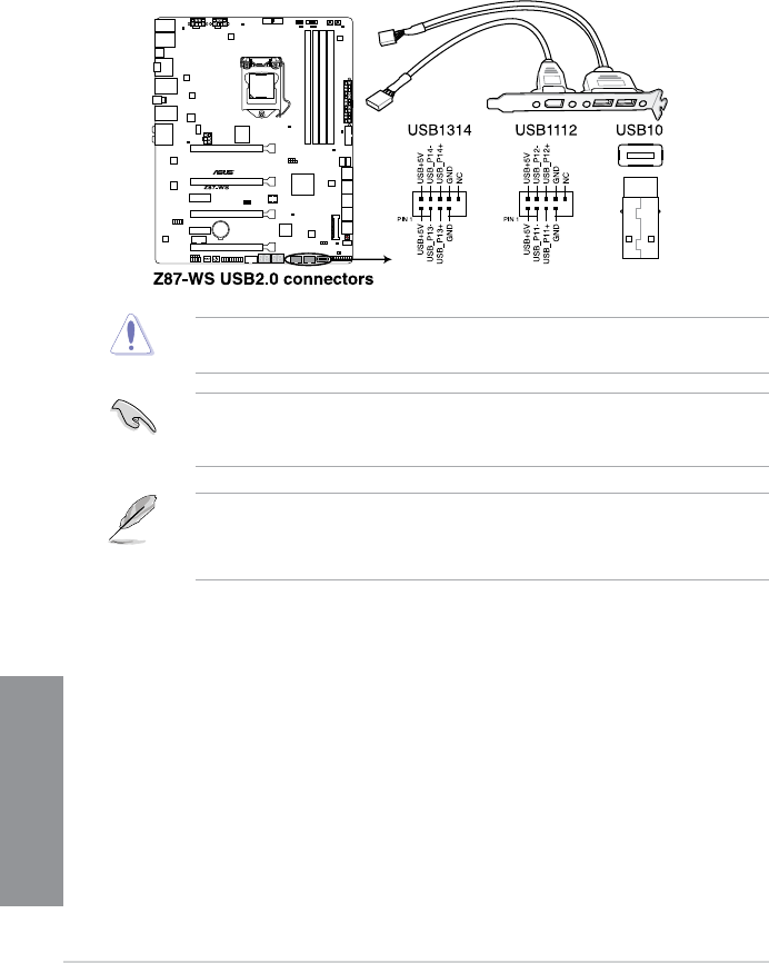
6. USB 2.0 connectors (10-1 pin USB1112, USB1314; USB10)
These connectors are for USB 2.0 ports. Connect the USB module cable to any of
these connectors, then install the module to a slot opening at the back of the system
chassis. These USB connectors comply with USB 2.0 specication that supports up to
480 MBps connection speed.