MODEL VSS-113 Installation Guide This product is intended for installation by a professional installer only! Any attempt to install this product by any person other than a trained professional may result in severe damage to a vehicle’s electrical system and components. www.astroflex.com Technical Support 800-461-8223 This resource is for authorized Astroflex dealers only.
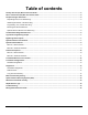
Table of contents Primary Harness (H1) Wire Connection Guide ..............................................................................................................2 Door Lock Harness (H2) Wire Connection Guide..........................................................................................................5 Peripheral Plug-In Harnesses..........................................................................................................................................
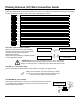
Primary Harness (H1) Wire Connection Guide This guide describes in detail the connection of each wire. Also included are possible applications of each wire. This system was designed with the ultimate in flexibility and security in mind. Many of the wires have more than one possible function. Please read carefully to ensure a thorough understanding of this unit.
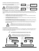
H1/4 ORANGE (+) Switched Ignition Input Connect this wire to the (+) 12 volts ignition wire. This wire is pre-wired to the starter kill relay and must show (+) 12 volts with the key in RUN position and during cranking. Take great care that this wire cannot be shorted to the chassis at any point.
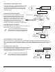
H1/9 GREY (-) 200 mA Dome-light Supervision Output Connect the H1/9 wire to the optional dome-light supervision relay as shown in the following diagram: NEVER use this wire to drive anything but a relay or a low-current input! This transistorized output can only supply 200 mA, and connecting directly to a light bulb, motor, or other highcurrent device will cause the module to fail.
H1/12 ORANGE/BLACK (-) 500 mA Ground When Armed Output This wire supplies a (-) ground as long as the system is armed. This output ceases as soon as the system is disarmed. The ORANGE/BLACK wire is pre-wired to control the starter kill relay. It can supply up to 500 mA of current. If using the H1/12 ORANGE/BLACK wire to activate an add-on accessory such as window automation, a diode must be installed to ensure proper operation. Insert the diode as shown in the following diagram.
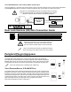
PROGRAMMING TOOL, 3-PIN BLACK PLUG The BLACK three-pin port is provided for programming of the unit. When using the programming tool, it is possible to configure any and all of the programmable functions. For more information please refer to the guide packaged with the programmer. MOUNTING THE RECEIVER/ANTENNA Receiver/antenna position should be discussed with the vehicle owner prior to installation, since the antenna may be visible to the vehicle’s operator.
Light Flash Programming Jumper This jumper is used to determine the light flash output. In the (+) position, the onboard relay is enabled and the unit will output (+)12V on the GREEN wire, H1/11. In the (-) position, the onboard relay is disabled. The GREEN wire, H1/11, will supply a 200 mA (-) output suitable for driving factory parking light relays. A standard automotive SPDT relay must be used on the H1/11 light flash output harness wire for parking light circuits that draw 10 amps or more.
4. Select a Feature. Press and release the Valet/Program switch the number of times corresponding to the feature you wish to change. For example, to access the third feature, press and release the switch three times. Then press the switch once more and HOLD it. The siren will chirp the number of times equal to the step you have accessed. 5. Program the Feature. While HOLDING the Valet/Program switch, you can toggle the feature on and off using the remote transmitter.
System Features Menus MENU #1 - BASIC FEATURES Items in bold text have been programmed to the default setting at the factory. Feature Number 1-1 1-2 1-3 1-4 1-5 1-6 1-7 1-8 1-9 1-10 One Chirp Setting Active arming Chirps ON Ignition controlled door locks ON Active locking only Panic with ignition on 0.
Feature Descriptions The features of the system are described below. Features that have additional settings that can be selected only when programming with the programming tool are indicated by the following icon: MENU #1 - BASIC FEATURES 1-1 ACTIVE/PASSIVE ARMING: When active arming is selected, the system will only arm when the transmitter is used. When set to passive, the system will arm automatically 30 seconds after the last door is closed.
MENU #2 - ADVANCED FEATURES 2-1 SIREN/HORN HONK: The system can be programmed to output pulses instead of a continuous output when the system is triggered. This is useful to honk the factory horn in applications where a siren is undesirable. Remember that the unit is only capable of supplying 1 amp of current. A relay will be required to interface with most factory horn systems. 2-2 SIREN DURATION 30/60 SECONDS: It is possible to program the unit to sound for 30 or 60 seconds during the triggered sequence.
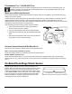
Transmitter/Receiver Learn Routine The system comes with two transmitters that have been taught to it. The system can store up to four different transmitter codes in memory. Use the following learn routine to add transmitters to the system or to change button assignments if desired. If the system was previously programmed using the programming tool, the learn routine may be locked.
To exit the learn routine: One long chirp indicates that Learn Routine has been exited. Learn Routine will be exited if any of the following occurs: Ignition is turned off. Door is closed. Valet/Program button is pressed too many times. More than 15 seconds elapse between steps. Transmitter Configurations The transmitters can be programmed with the standard configurations by using the Auto Learn functions in the Transmitter/Receiver Learn Routine.
TABLE OF ZONES Zone No. Trigger type Input description 1 Instant 2 3 On-board shock sensor Two-stage, progresses from 4 Multiplexed Input H1/7 BLACK/WHITE - Connect to optional hood/trunk pins. Heavy impact detected by the on-board shock sensor. Door switch circuit. H1/8 WHITE or H1/6 PURPLE warning to full alarm BLUE and GREEN wires of optional sensor plug. Inputs shorter than 0.8 seconds will trigger a Warn Away response, while inputs longer than 0.
Nuisance Prevention® Circuitry Nuisance Prevention® Circuitry bypasses any zone that triggers the system more than three times within a one hour period. For a full description of NPC® operations refer to the owner's manual. When testing the systems sensor and trigger inputs reset NPC® by turning on the ignition after every third system trigger. Door input does not respond with the progressive trigger, but with immediate full alarm.
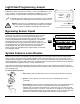
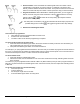
Wiring Quick Reference Guide Valet / Program Switch Programming tool PINK (-) CHANNEL 2 VALIDITY OUTPUT (MAY REQUIRE RELAY) Antenna / Receiver RED (+) CONSTANT POWER INPUT RED/WHITE (+) SIREN OUTPUT ORANGE (+) SWITCHED IGNITION INPUT , ZONE 5 BLACK (-) CHASSIS GROUND INPUT PURPLE (+) DOOR TRIGGER INPUT, ZONE 3 Shock sensor adjustment BLACK/WHITE (-) INSTANT TRIGGER INPUT, ZONE 1 WHITE (-) DOOR TRIGGER INPUT, ZONE 3 GREY (-) 200 mA DOME-LIGHT SUPERVISION OUTPUT LED Parking Light Polarity Selector P