
Installation manual

13
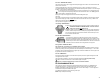
P4-3: Green: PARKING LIGHT OUTPUT
This wire provides a positive output to trigger the vehicle's parking light circuit to add a visual confirmation when the
module receives commands.
Locate the parking light circuit. If the circuit is controlled by a ground (-) signal, it is possible to use one of the
four programmable outputs set in "Parking lights" mode. That will leave this positive output free so it can be configure
in Stage 2 – Level 2 page 23 for different functions.
Be sure the circuit you found is a Parking light circuit and not a dash light circuit, as a dash light circuit will
have a voltage that varies depending on the position of the dash dimmer control. Use a DMM (digital multi-
meter) instead of a test light to test this circuit.
Warning. This output cannot supply more than 30A, combined with the Ignition output.
This means:
If this output is configured to energize a circuit while the Ignition output is energized, be sure that both, the “Ignition”
output and the “Parking Light” output, combined,
won’t draw more than 30A. If this is the case, you better use an
external relay or the built in P5 relay for your application.
This output cannot be program as “Accessory”.
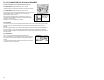
P4-4: Orange: IGNITION OUTPUT
Provides power to the vehicle's ignition circuit (which is required to make the engine run).
THIS CIRCUIT IS PART OF A SECURITY DEVICE. It must be connected
directly to the vehicle’s main
ignition circuit.
Some newer vehicles can have multiple ignition wires in the main ignition switch harness.
Therefore, additional relays will have to be added (through programmable outputs P2-13
to P2-16 to ensure vehicle’s circuits maintain its isolation. The P5 built-in relay can also
be use to interface with these wires.
P4-5: Dark Blue: STARTER OUTPUT
+12V output used to supply power to the starter motor in the vehicle. This is another
circuit that can potentially hold multiple wires. Additional relays must be added to ensure
vehicle’s circuits maintain its isolation. (See Programmable outputs P2-13 to P2-16.) The
P5 built-in relay can also be used to interface with these wires. This wire must be hooked
to the starter motor side of the start circuit if using the starter cut relay option.
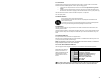
P4-6: Light Blue: STARTER CUT INPUT
Only required if the “over-cranking” or the “Antitheft” option is installed.
Input wired to an internal relay, which allows the module to cut off the starter circuit when the vehicle is running on
remote start preventing over-cranking of the Start. When the Antitheft option is enabled in Stage 1 – Level 4 of the
programming, the cut-off will be engaged when the Ignition key is ON and the antitheft active. This wire goes to the
key Cylinder side of the Start circuit that you cut.
P4-7: Red: POWER INPUT
Power input wire that is protected by a 30A in-line fuse that provides power for the “Ignition-Orange wire” and the
“Park Lights-Green wire” outputs.
This wire should be connected to a circuit in the main ignition switch harness that can provide 30 amps.
When there is more than one feed circuit, use the circuit that supplies most power.
Under no circumstances rating of the fuse on this circuit should be modified.
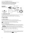
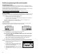
P5: PROGRAMMABLE RELAY
This is a three-pin connector connected to an internal standard automotive style relay, i.e. COMMON-30, N.O.
(normally open)-87 and N.C. (normally closed)-87A.This connector is there to save an external relay in your
installation. The installation of this relay requires a maximum of 3 wires. Refer to Stage 1 - Level 9 on page 20 for
more details about the options available on this output.
Cut to White wire supplied in the box for the wiring of this output.
NOTE: Always use adequate fuse rating.