

Assembly Instructions
AN2009-01
The Press-In Process
Application Note 9 V2.2, 2015-02
3 The Press-In Process
This section deals with the necessary press-in forces and tools for the modules.
The PressFIT module is inserted in a printed circuit board by press-in. The press-fitting can be
performed using a simply toggle lever press or a machine. A press-in tool that records the necessary
force and the travel distance is to be recommended. Consistent quality is assured in this way. The
press-fitting speed should not be lower than 25 mm/min according to IEC 60352-5. A lower press-fitting
speed can lead to increased press-in forces and to deformation of the pins or a not gas-tight
connection.
Note that during the press-in process the placement area of the printed circuit board and the pressing
area of the pressure plate must be parallel to each other. The pressure plate should be mechanically
fixed in position without any play. The module is then pressed into the printed circuit board with a
regular movement.
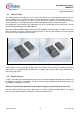
The module pins should penetrate the printed circuit board during press-in until the four standoffs on
the module or optional distance keepers as described in chapter 12 make contact with the board.
By adhering to the principles stated above, a smooth insertion process for the two components
(Easy1B and Easy2B) can be achieved.
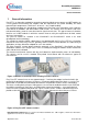
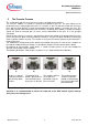
The following illustrations show the press-in process as it is implemented in the laboratory.
a)
The press is aligned
so that one part of the
tool is directly above
the other.
b)
The printed circuit
board is placed on the
tool and held in place
by the pins on the tool.
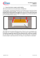
c)
The module is placed
on the tool and
positioned using the
pins on the tool.
d)
The module contacts
are pressed onto the
printed circuit board by
pressing the upper tool
part downwards.
Figure 5: Press-In process of an Easy module
Attention! It is recommendable to protect the underside of the IGBT module against damage
during the press-fitting process.