


Assembly Instructions
AN2009-01
Requirements for Printed Circuit Boards
Application Note 7 V2.2, 2015-02
2 Requirements for Printed Circuit Boards
The PressFIT technology used in the Easy modules has been inspected and qualified by Infineon AG
for standard FR4 printed circuit boards with tin (chemically) (IEC 60352-5 + IEC60747-15). If other
handling technologies are to be used in the production of printed circuit boards, they would have to be
tested, inspected and qualified.
Requirements for the PCB material
Double-sided printed circuit board according to IEC 60249-2-4 or IEC 60249-2-5.
Multilayer printed circuit board according to IEC 60249-2-11 or IEC 60249-2-12.
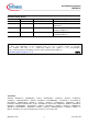
Table 1: Requirements for a printed circuit board
min.
typ.
max.
Hole drill diameter
1.12 mm
1.15 mm
Copper thickness in hole
> 25 µm
< 50 µm
Metallization in hole
< 15 µm
End hole diameter
1.09 mm
Copper thickness of
conductors
35 µm
70 µm
105 µm
400 µm
Metallization of circuit board
Tin (chemically)
Metallization of pin
Tin (galvanic)
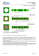
In order to ensure that the PressFIT contact sits securely in the printed circuit board, the specification of
the hole given in Table 1 must be adhered to.
If the specification of PressFIT holes is limited to just the finished dimension (i.e., the metallized hole),
different drill sizes could be used depending on the printed circuit board manufacturer and production
philosophy, and also different metallization thicknesses could be provided. This would have the
consequence that other results would be obtained that would have to be rejected for quality assurance
reasons.
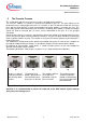
The recommendation still applies that the hole in the printed circuit board is to be drilled during
manufacture with a drill size of 1.15 mm, and should not be milled. Experience has shown that a final
hole diameter of between 1.12 mm and 1.15 mm is obtained under consideration of the runout
tolerances of the spindles after drilling due to shrinking of the FR4 material.
With a copper thickness of 25 µm to 50 µm in the hole and a tin layer of about 1 µm for tin applied
chemically, an end hole diameter is obtained as the test dimension. Due to the thinner tin layer
thickness, this diameter is always higher than the value of 1 mm stated in the standard (IEC 60352-5).
The final hole diameter, under consideration of the drilling diameter, copper thickness and tin layer, is
typically between 1.02 mm and 1.09 mm.