


Assembly Instructions
AN2009-01
Multi-Module and Automotive Application
Application Note 26 V2.2, 2015-02
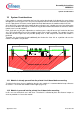
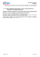
12.0 ±0.35
air gap
max 12.45
(H)
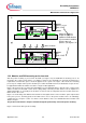
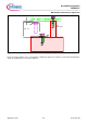
Figure 18: Zoom illustration of final system assembly. (drawing not true to scale)
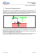
Please note that using this press-concept with a remaining air gap does not allow to screw down the PCB to the
stand-offs (guiding holes) as shown in chapter 6.