


Assembly Instructions
AN2009-01
Multi-Module and Automotive Application
Application Note 25 V2.2, 2015-02
a)
Infineon
Infineon
Infineon
FxxRxxW1xx_B11A
FxxRxxW1xx_B11A
FxxRxxW1xx_B11A
max 12.45
(H)
b)
Infineon
Infineon
Infineon
FxxRxxW1xx_B11A
FxxRxxW1xx_B11A
FxxRxxW1xx_B11A
cooling system
max 12.45
(H)
c)
Infineon
Infineon
Infineon
FxxRxxW1xx_B11A
FxxRxxW1xx_B11A
FxxRxxW1xx_B11A
d)
Infineon
Infineon
Infineon
FxxRxxW1xx_B11A
FxxRxxW1xx_B11A
FxxRxxW1xx_B11A
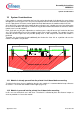
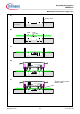
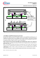
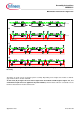
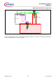
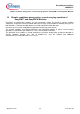
Figure 17: Mounting example of the PCB and module to the cooling system. (drawing not true
to scale)
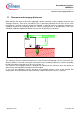
The Figure 18 shows a zoom of the final system assembly. Depending on the height of the module a small air
gap remains between module and PCB.
As the value (H) of Figure 17b must not be higher than the module to PCB height of Figure 17a, it is
ensured that no pull forces are applied to the power modules, which would be critical in consideration of the
thermal contact between module and heat sink.