


Assembly Instructions
AN2009-01
Multi-Module and Automotive Application
Application Note 24 V2.2, 2015-02
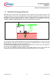
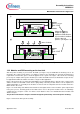
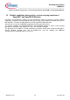
f)
max 12.45
Infineon
FxxRxxW1xx_B11A
Distance keeper
g)
press-in force
12.0
±0.35
Infineon
FxxRxxW1xx_B11A
max 12.45
(H)
Figure 16: Press-in of the power modules. (drawing not true to scale)
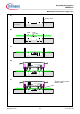
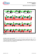
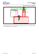
12.2 Modules and PCB mounting on the heat sink
After the power module(s) is pressed into the PCB (see Figure 17a), the PCB with the module(s) has to be
mounted to the cooling system. Please see chapter 7 and 8 for more information on heat sink, thermal grease
requirements and how the grease should be applied to the system. The Figure 17b-d shows the mounting
process by an example of three power modules pressed into the PCB. However, the illustrated concept can also
be applied with a different number of modules or single module application.
Figure 17b shows the process where the PCB with the pre-assembled modules is placed on the cooling system
and the modules are fixed with screws via the spring clamp of the Easy module. Please refer to chapter 9 for
detailed information on assembly of the modules on the heat sink. It is important to fix the modules before the
PCB is fixed to the cooler!
Figure 17c shows fixing of the PCB to the heatsink. As the height tolerance of the module is quasi compensated
in the press process, the fixing points for the PCB can be close to the power modules. This is an advantage
compared to the concept in section 10.1 where >=5cm distances has to be maintained between module and
distance keepers.
The position of the distance keepers should be designed symmetrically around the power module(s).
Figure 17d shows the final system assembly.
Adjust the distance
keeper to achieve a
module to PCB distance
(H) of maximal 12.45mm
after the press-in
process (see Figure 17a)