


Assembly Instructions
AN2009-01
Multi-Module and Automotive Application
Application Note 22 V2.2, 2015-02
12 Multi-Module and Automotive Application
An increasing number of applications require the mounting of several power modules on the PCB.
Furthermore, new power module applications, like automotive hybrid electrical vehicles and full electric
vehicles (H)EV, have high requirements on vibration and mechanical shock robustness. In such
applications the height tolerance of the modules has to be considered in the mounting concept in order
to avoid a mechanical deformation of the PCB or unwanted forces on the modules and PressFIT pins.
Please note that the following instruction shall be regarded as additional information to the general
mounting instructions before. The chapter focuses on mounting concept of the module, taken into
account the height tolerance. General recommendations like PCB requirements, press speed, heat sink
requirements, etc. are unaffected by the following instructions.
12.1 Modules press-in into the PCB
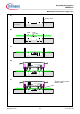
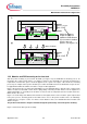
Figure 16 shows the press-in process of the power modules into the PCB. This process is quite similar
to chapter 3.
Figure 16a shows the bottom side of the press-tool with guiding domes, which are useful for a pre-
alignment. In Figure 16b the PCB is placed into the press-tool, whereby the correct placement is
obtained by the guiding domes of the press-tool.
Figure 16c shows the press-tool with the PCB ready for module assembly.
In Figure 16d the module is placed on the guiding elements. The module is released and the module
pins will insert now into the PCB.
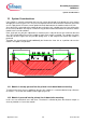
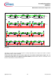
In Figure 16e shows the state where the module pins are inserted into the PCB. The module is now
placed even to the press-tool and the pin touches the PCB at the beginning of the active press-zone,
which starts at about 2.5mm from the pin top. If the module is uneven to the press-tool or pins are not
inserted (module about 2.5mm higher than the normal case shown here), than the assembly should be
corrected before damaging pins in the later press-in process.
In Figure 16f the top press-tool with the distance keeper is shown.
Figure 16g shows the controlled way-force press-in process. The press-process stops by the increasing
force between the PCB and this distance keeper. It is correct, if the press-in process is stopped before
the PCB is on the module housing. Thus, the distance of the module backside to the PCB is
independent of the module height.
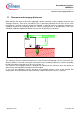
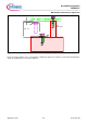
Please note: It is possible to press the module tighter to the PCB than the maximum 12.45mm. This
will increase the overlapping zone in the active press zone (contact area: pin to PCB). Please do not
forget to lower the fixing elements of the cooling system (Figure 17b) accordingly, if the modules are
pressed tighter to the PCB! The value (H) of Figure 17b must not be higher than the module to
PCB height of Figure 17a! A force of the PCB on the module in direction to the cooling system is
uncritical and is desired as it improves the thermal contact.