


Assembly Instructions
AN2009-01
Clearance and creepage distances
Application Note 21 V2.2, 2015-02
11 Clearance and creepage distances
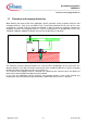
When defining the layout of the PCB, application specific standards, mainly regarding clearance and
creepage distances, have to be considered. This is particularly important for the area of the screw
clamp which is located under the printed circuit board. In order to meet the respective requirements
regarding clearance and creepage distances, current carrying devices or through-holes in this area
should be avoided or additional isolation measures like lacquering must be taken.
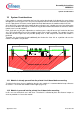
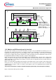
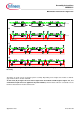
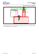
Figure 15: Air path between clip and PCB
The minimum clearance distance between the screw and the PCB depends on the screw itself. The
distance will be 6.8 mm with a hexagon socket head screw according to DIN 912, a washer according
to DIN 125 and the clamp which can be seen in Figure 15.
The clearance and creepage distances specified in the datasheet are minimum values irrespective of
other devices that would be mounted close to the module.
In any case, the application specific clearance and creepage distances have to be checked and
compared to relevant standards and guaranteed by suitable constructive means, if required.