

Assembly Instructions
AN2009-01
System Considerations
Application Note 20 V2.2, 2015-02
10 System Considerations
If the module is correctly mounted to the heat sink and to the printed circuit board, the screw clamps
will apply the necessary pressure. This pressure together with the correct amount of thermal grease will
ensure a low thermal resistance and an optimal thermal flow between the module and the heat sink.
Since the PCB is connected to the module by pressed-in pins only, suitable measures have to be taken
to ensure that vibrations are kept at a minimum. Any possible movement between the terminals and the
module case has to be avoided.
Each single pin may only be subjected to a maximum press and pull force of 6 N vertical to the heat
sink. The overall pulling force to the module of 20 N must not be exceeded. The compressive force
could be 10 times higher than the possible pulling force. A low compressive load to the module is
preferred.
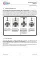
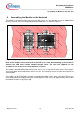
Therefore, the circuit board should additionally be fixed to the heat sink at a position close to the
module. Two options are possible:
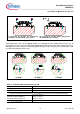
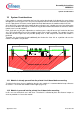
Figure 14: Fixing the printed circuit board
10.1 Module is already pressed into the printed circuit board before mounting
To minimise the forces that are applied to the pins of a module, it is recommended to keep a distance
of at least x = 5 cm from the module’s outer edges (Figure 14).
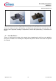
10.2 Module is pressed into the printed circuit board after mounting
In this case no mechanical stress will occur. Therefore it is allowed to place the distance keeper as
close as possible x ≤ 5 cm to the module.
Infineon
Distance keeper h = 12 mm