

Assembly Instructions
AN2009-01
Assembling the Module on the Heat sink
Application Note 18 V2.2, 2015-02
9 Assembling the Module on the Heat sink
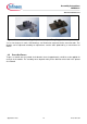
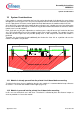
The module is mounted onto the heat sink using M4 screws. It is also possible to use an additional flat
washer. The heat sink has to be provided with threaded holes as shown in Figure 11.
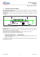
Figure 11: Spacing of the thread holes
Note: If the module is first pressed in to the PCB or if a later disassembling of the module is
desired, the PCB must contain suitable through holes. The hole size depends on the
screwdriver size or the screw’s head diameter or washer.
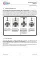
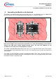
The module should be positioned onto the heat sink in such a way that the holes of the screw clamps
are exactly above the threaded holes of the heat sink. The mounting surface must be clean and free of
contamination.
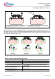
The module can be fastened by screwing in and tightening both screws at the same time (Figure 12a)
or by holding down the module during the mounting process with a force of approximately 10 N so that
the module cannot rise up (Figure 12b).