
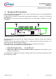

Assembly Instructions
AN2009-01
Mounting a PCB to the Module
Application Note 15 V2.2, 2015-02
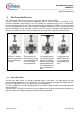
6 Mounting a PCB to the Module
To fix a PCB onto the module additional screws can be used if desired. These screws will be tightened
into the stand offs of the module.
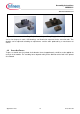
An electronically controlled or at least slowly turning electric screwdriver n ≤ 300 rpm is the preferred
mounting tool.
Due to the lack of accuracy we do not recommend the use of pneumatic screwdrivers or manual
screwdrivers.
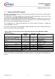
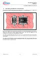
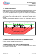
Figure 10: Detailed view of the assembly insert
The effective length of the thread in the stand-off should have a minimum of 4mm and a maximum
length of 8 mm.
The initial 1.5 mm of the mounting stand-off serves as guidance only and cannot take any force. The
thread in the plastics will form itself by screwing.
For the choice of the screw length the given PCB thickness has to be taken into account.
The following screws are tested to fix the PCB to the module:
Ejot PT WN 1451 K25*10 A2K M
max
=0,45Nm ±10%
Ejot DELTA PT WN 5451 K25*8 M
max
=0,4Nm ±10%
Metric screws: M2.5*x – for example, M2.5*8 or M2.5*10 depending on the thickness of the
printed circuit board used
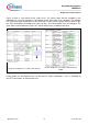
To avoid damage or splitting of the stand-off, straight insertion of the screw into the stand-off has to be
observed during assembly.
Infineon