

Assembly Instructions
AN2009-01
The Press-Out Process
Application Note 11 V2.2, 2015-02
4 The Press-Out Process
This section deals with the necessary press-out forces and tools for the modules.
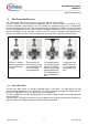
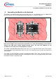
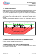
PressFIT modules are removed with the appropriate tools as shown in Figure 7 and Figure 8. The
printed circuit board is placed with the PressFIT module in the apparatus (tray). Force is applied with
the extrusion plate on the PressFIT pins that protrude from the printed circuit board. The press-out tools
must be aligned parallel to each other so that the individual components (such as the printed circuit
board and module) are not damaged. Once the PressFIT zone has exited the PCB (printed circuit
board), the module falls into the tray in the lower part of the tool and is separated from the board.
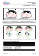
Step 1:
The press is aligned
so that one part of the
tool is directly above
the other.
Step 2:
The printed circuit
board is placed in the
extrusion tool with the
PressFIT module
facing downward.
Step 3:
The module contacts
are extruded from the
printed circuit board
by pressing the upper
tool part downwards.
The module falls into
the tray of the lower
tool.
Step 4:
The printed circuit
board and module
can be separately
removed from the
tool.
Figure 7: Extrusion of an Easy module
4.1 Press-Out Tools
The press-out tools consist (as already mentioned above) of two parts. The upper part of the tool
presses directly downwards on the module pins. The lower part of the tool holds the module with the
printed circuit board and serves as a base for the pressing operation.
The disassembly tools must be aligned parallel to each other in order to obtain an equally distributed
extrusion process.
The dimensions of the press-out tool must be considered when designing the printed circuit board so
that the components positioned about the module will not be damaged.