

Assembly Instructions
AN2009-01
The Press-In Process
Application Note 10 V2.2, 2015-02
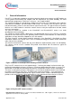
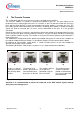
3.1 Press-In Tools
The following tools that help pressing in and out the module are recommended for the two Easy B
Series modules. Figure 6 shows these press tools for the two housing types Easy 1B and Easy 2B.
Each of the tools has two parts. First there is a part that presses against the underside of the module
and second, there is a part for holding the printed circuit board in place to be pressed against.
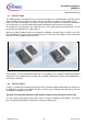
No components can be placed in the mounting areas of this special type of press-fitting tool. This will
prevent damage during the press-fitting process.
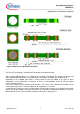
When press-fitting multiple modules onto a printed circuit board, arrange the press-in tool in such a way
that the modules are on the same level after the pressing. In this way, the modules can be mounted on
the heat sink with a good thermal connection.
Figure 6: Press-fitting tools for Easy1B (shown left), Easy2B (shown right).
CAD drawings can be requested for both tools. The drawing can be adjusted according to different
requirements (e.g. module pinning and top side assembly of other parts) and the tools produced by a
manufacturer of choice.
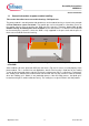
3.2 Press-In Forces
To press a module onto a printed circuit board a force of between approximately 60 N and 100 N must
be applied for each pin in the module. The press-in forces vary according to the diameter of the hole
and copper metallization in the PCB.
Attention! The maximum applied force per module during pressing should not exceed 4 kN.
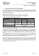
The press-fitting speed should not be lower than 25 mm/min according to IEC 60352-5. The typical
press-in speed for automated assembly lines will be up to 450 mm/min.