EA S Y - Pre ssFIT Po wer Mod ul es Easy PIM Easy PACK Easy Automotive Asse mbl y Instr uc tio ns AN2009-01 Applic atio n N ote V2.
Edition 2015-02 Published by Infineon Technologies AG, 81726 Munich, Germany. © 2015 Infineon Technologies AG All Rights Reserved. LEGAL DISCLAIMER THE INFORMATION GIVEN IN THIS APPLICATION NOTE IS GIVEN AS A HINT FOR THE IMPLEMENTATION OF THE INFINEON TECHNOLOGIES COMPONENT ONLY AND SHALL NOT BE REGARDED AS ANY DESCRIPTION OR WARRANTY OF A CERTAIN FUNCTIONALITY, CONDITION OR QUALITY OF THE INFINEON TECHNOLOGIES COMPONENT.
Assembly Instructions AN2009-01 Document Change History Date Version Changed By Change Description 2009-01 V1.0 M. Buschkühle initial 2011-06 V2.0 T. Reiter Added chapter 12: automotive applications 2014-02 V2.1 M. Buschkühle Additional integration of chapter 14 and change in Chapter 13 2015-02 V2.2 T. Reiter Update of Template. Revised chapter 12. Added chapter 1.1.
Assembly Instructions AN2009-01 Table of Contents 1 1.1 General Information .......................................................................................................................... 5 General Information on power module handling ................................................................................. 6 2 Requirements for Printed Circuit Boards ....................................................................................... 7 3 3.1 3.2 The Press-In Process .............
Assembly Instructions AN2009-01 General Information 1 General Information PressFIT is an alternative method for connecting control and load current contacts on IGBT modules to a PCB (printed circuit board) that complies with the requirements for greater durability, the trend towards higher temperatures, RoHS and – of course – very simple handling. This contact technology has already been employed for years now in the automotive sector under the most difficult of conditions and with medium-sized currents.
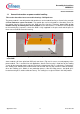
Assembly Instructions AN2009-01 General Information 1.1 General Information on power module handling This section describes forces on module housing – DCB push-out The power module is not designed to withstand forces on the module housing as shown in the example of Error! Reference source not found.. The module pins are here located on a flat table. Forces on the module housing (Fp) are pushing the DCB out of the housing. Therefore, forces (Fp) on the module housing at handling have to be avoided.
Assembly Instructions AN2009-01 Requirements for Printed Circuit Boards 2 Requirements for Printed Circuit Boards The PressFIT technology used in the Easy modules has been inspected and qualified by Infineon AG for standard FR4 printed circuit boards with tin (chemically) (IEC 60352-5 + IEC60747-15). If other handling technologies are to be used in the production of printed circuit boards, they would have to be tested, inspected and qualified.
Assembly Instructions AN2009-01 Requirements for Printed Circuit Boards Figure 4 Structure of a printed circuit board The PressFIT technology is qualified for FR4 printed circuit board material. After a reflow soldering process is carried out on a printed circuit board, the module can be pressed into the board without difficulty. The retention forces of the press-fitted pins are not diminished.
Assembly Instructions AN2009-01 The Press-In Process 3 The Press-In Process This section deals with the necessary press-in forces and tools for the modules. The PressFIT module is inserted in a printed circuit board by press-in. The press-fitting can be performed using a simply toggle lever press or a machine. A press-in tool that records the necessary force and the travel distance is to be recommended. Consistent quality is assured in this way.
Assembly Instructions AN2009-01 The Press-In Process 3.1 Press-In Tools The following tools that help pressing in and out the module are recommended for the two Easy B Series modules. Figure 6 shows these press tools for the two housing types Easy 1B and Easy 2B. Each of the tools has two parts. First there is a part that presses against the underside of the module and second, there is a part for holding the printed circuit board in place to be pressed against.
Assembly Instructions AN2009-01 The Press-Out Process 4 The Press-Out Process This section deals with the necessary press-out forces and tools for the modules. PressFIT modules are removed with the appropriate tools as shown in Figure 7 and Figure 8. The printed circuit board is placed with the PressFIT module in the apparatus (tray). Force is applied with the extrusion plate on the PressFIT pins that protrude from the printed circuit board.
Assembly Instructions AN2009-01 The Press-Out Process Figure 8: Press-out tools for Easy1B (left illustration) and Easy2B (right illustration) modules Just as for the press-in tools, CAD drawings can likewise be requested for the extrusion tools. The drawing can be adjusted according to requirements and the tools produced by a manufacturer of choice. 4.2 Press-Out Forces To press a module out of a printed circuit board a force of approximately >40 N has to be applied for each pin in the module.
Assembly Instructions AN2009-01 Quality of PressFIT Contacts 5 Quality of PressFIT Contacts PressFIT is an alternative solution for connecting control and load current contacts on IGBT modules with a printed circuit board. The requirements for greater durability, the trend towards higher temperatures and absence of lead and – of course – very simple handling are continuously growing.
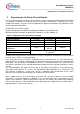
Assembly Instructions AN2009-01 Quality of PressFIT Contacts Figure 9 shows a small extract of the various tests. The extract shows that the conditions in the individual tests are to be regarded as considerably stricter than stated in the standards. For example, the significantly higher temperatures or the loads that are up to 5 times greater during a corrosive gas test (H2S concentration according to the norm: 10 ppm / H2S concentration in the test: 50 ppm).
Assembly Instructions AN2009-01 Mounting a PCB to the Module Mounting a PCB to the Module 6 To fix a PCB onto the module additional screws can be used if desired. These screws will be tightened into the stand offs of the module. An electronically controlled or at least slowly turning electric screwdriver n ≤ 300 rpm is the preferred mounting tool. Due to the lack of accuracy we do not recommend the use of pneumatic screwdrivers or manual screwdrivers.
Assembly Instructions AN2009-01 Condition of the Heat Sink for Module Assembly Condition of the Heat Sink for Module Assembly 7 The power loss occurring in the module has to be dissipated via heatsink in order not to exceed the maximum permissible temperature Tvjop specified in the datasheets during operation.
Assembly Instructions AN2009-01 Applying the Thermal Grease 8 Applying the Thermal Grease Due to the individual surface shape (e.g. roughness and flatness) of the heatsink and the module these do not touch across the entire area so that a certain localized separation between the two components cannot be avoided. To dissipate the losses occurring in the module and to achieve a good flow of heat into the heatsink, all localized cavities have to be filled with a thermal compound.
Assembly Instructions AN2009-01 Assembling the Module on the Heat sink 9 Assembling the Module on the Heat sink The module is mounted onto the heat sink using M4 screws. It is also possible to use an additional flat washer. The heat sink has to be provided with threaded holes as shown in Figure 11. Figure 11: Spacing of the thread holes Note: If the module is first pressed in to the PCB or if a later disassembling of the module is desired, the PCB must contain suitable through holes.
Assembly Instructions AN2009-01 Assembling the Module on the Heat sink Infineon Infineon Infineon a) Fastening the module by simultaneous screwing in and tightening of the screws. Infineon b) Fastening the module while holding down the module during screwing. Figure 12: Module fastening options Alternatively one screw can be applied initially. It is important that the module does not rise up.
Assembly Instructions AN2009-01 System Considerations 10 System Considerations If the module is correctly mounted to the heat sink and to the printed circuit board, the screw clamps will apply the necessary pressure. This pressure together with the correct amount of thermal grease will ensure a low thermal resistance and an optimal thermal flow between the module and the heat sink.
Assembly Instructions AN2009-01 Clearance and creepage distances 11 Clearance and creepage distances When defining the layout of the PCB, application specific standards, mainly regarding clearance and creepage distances, have to be considered. This is particularly important for the area of the screw clamp which is located under the printed circuit board.
Assembly Instructions AN2009-01 Multi-Module and Automotive Application 12 Multi-Module and Automotive Application An increasing number of applications require the mounting of several power modules on the PCB. Furthermore, new power module applications, like automotive hybrid electrical vehicles and full electric vehicles (H)EV, have high requirements on vibration and mechanical shock robustness.
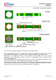
Assembly Instructions AN2009-01 Multi-Module and Automotive Application a) guiding dome Press-tool b) PCB PCB assembly c) d) FxxRxxW1xx_B11A Infineon e) FxxRxxW1xx_B11A Infineon Application Note 23 The pins are inserted into the PCB. V2.
Assembly Instructions AN2009-01 Multi-Module and Automotive Application f) Distance keeper max 12.45 FxxRxxW1xx_B11A Infineon Adjust the distance keeper to achieve a module to PCB distance (H) of maximal 12.45mm after the press-in process (see Figure 17a) g) press-in force 12.0 ±0.35 (H) max 12.45 FxxRxxW1xx_B11A Infineon Figure 16: Press-in of the power modules. (drawing not true to scale) 12.
Assembly Instructions AN2009-01 Multi-Module and Automotive Application a) Infineon FxxRxxW1xx_B11A Infineon Infineon FxxRxxW1xx_B11A FxxRxxW1xx_B11A (H) max 12.45 b) Infineon FxxRxxW1xx_B11A Infineon Infineon FxxRxxW1xx_B11A FxxRxxW1xx_B11A (H) max 12.
Assembly Instructions AN2009-01 Multi-Module and Automotive Application air gap (H) max 12.45 12.0 ±0.35 Figure 18: Zoom illustration of final system assembly. (drawing not true to scale) Please note that using this press-concept with a remaining air gap does not allow to screw down the PCB to the stand-offs (guiding holes) as shown in chapter 6. Application Note 26 V2.
Assembly Instructions AN2009-01 Storage and Transport 13 Storage and Transport During transport and storage of the modules, extreme forces through shock or vibration have to be avoided as well as extreme environmental influences. Storage of the modules at the limits of the temperature specified in the datasheet is possible, but not recommended.
Assembly Instructions AN2009-01 Climatic conditions during active, current carrying operation of EasyPIM™ and EasyPACK Modules 14 Climatic conditions during active, current carrying operation of EasyPIM™ and EasyPACK Modules EasyPIM™ and EasyPACK modules are not hermetically sealed. The housings and the molding compound, used for the electrical isolation within the housing, are permeable for humidity and gases in both directions. Therefore humidity differences will be equalized in both directions.
w w w . i n f i n e o n .