
User's Manual
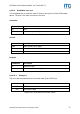
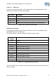
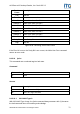
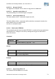
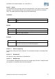
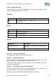
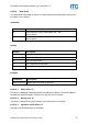
Table Of Contents
- Safety Instructions / Warning - Read before start-up!
- Preface
- 1 Scope
- 2 Extended Documentation
- 3 Definitions and Abbreviations
- 4 Supported tags
- 5 The mifare® Transponder Family
- 6 ISO 14443 Type B
- 7 Hardware
- 8 Software for contactless interface functions
- 8.1 ASCII Protocol
- 8.2 Binary Protocol
- 8.3 Register Set
- 8.3.1 EEPROM memory organization
- 8.3.2 Unique device ID (00h – 04h)
- 8.3.3 Station ID (0Ah)
- 8.3.4 Protocol configuration (0Bh)
- 8.3.5 BAUD, Baud rate control register (0Ch)
- 8.3.6 Command Guard Time (0Dh)
- 8.3.7 OPMODE, operating mode register (0Eh)
- 8.3.8 Single Shot Time-out (0Fh)
- 8.3.9 Protocol configuration 2 (13h)
- 8.3.9.1 Disable multi-tag reset (default 0)
- 8.3.9.2 Disable start-up message (default 0)
- 8.3.9.3 Enable binary frame v2 (default 0)
- 8.3.9.4 Noisy Environment (default 0)
- 8.3.9.5 Reset Recovery Time Multiplier (default 0)
- 8.3.9.6 Enable ISO14443 B Anti-collision (default 0)
- 8.3.9.7 Disable ISO 14443-4 Error Handling (default 0)
- 8.3.10 Reset Off Time (14h)
- 8.3.11 Reset Recovery Time (15h)
- 8.3.12 Application Family Identifier (16h)
- 8.3.13 Selection Time-out ISO 14443A (17h)
- 8.3.14 Selection Time-out ISO 14443B (18h)
- 8.3.15 Selection Time-out SR176 (19h)
- 8.3.16 Protocol configuration 3 (1Bh)
- 8.3.17 User data (80h - EFh)
- 8.4 Instruction Set
- 8.4.1 Overview
- 8.4.2 Error Codes
- 8.4.3 Common commands
- 8.4.3.1 Test Continuous Read
- 8.4.3.2 Continuous Read
- 8.4.3.3 Set LED
- 8.4.3.4 DES encryption / decryption of data
- 8.4.3.5 Get ID
- 8.4.3.6 Multi-Tag Selection / List
- 8.4.3.7 Include tag type
- 8.4.3.8 Exclude tag type
- 8.4.3.9 Set tag type
- 8.4.3.10 Set Configuration Flags
- 8.4.3.11 Set Configuration Register
- 8.4.3.12 Antenna power on/off
- 8.4.3.13 Read/Write user port
- 8.4.3.14 Quiet
- 8.4.3.15 Read block
- 8.4.3.16 Read reader EEPROM
- 8.4.3.17 Select
- 8.4.3.18 Get Version
- 8.4.3.19 Write DESFire key
- 8.4.3.20 Write master key
- 8.4.3.21 Write block
- 8.4.3.22 Write EEPROM
- 8.4.3.23 Reset
- 8.4.3.24 Field Reset
- 8.4.4 ISO 14443 Type A only commands
- 8.4.5 SR176 only commands
- 8.4.6 DESFire command set
- 8.4.6.1 Authenticate
- 8.4.6.2 Change Key Settings
- 8.4.6.3 Get Key Settings
- 8.4.6.4 Change Key
- 8.4.6.5 Get Key Version
- 8.4.6.6 Create Application
- 8.4.6.7 Delete Application
- 8.4.6.8 Get Application IDs
- 8.4.6.9 Select Application
- 8.4.6.10 Format PICC
- 8.4.6.11 Get Version
- 8.4.6.12 Get File IDs
- 8.4.6.13 Get File Settings
- 8.4.6.14 Select File
- 8.4.6.15 Change File Settings
- 8.4.6.16 Create Standard Data File
- 8.4.6.17 Create Backup Data File
- 8.4.6.18 Create Value File
- 8.4.6.19 Create Linear Record File
- 8.4.6.20 Create Cyclic Record File
- 8.4.6.21 Delete File
- 8.4.6.22 Read Data / Records
- 8.4.6.23 Data files
- 8.4.6.24 Record file
- 8.4.6.25 Write Data / Record
- 8.4.6.26 Get Value
- 8.4.6.27 Credit
- 8.4.6.28 Debit
- 8.4.6.29 Limited Credit
- 8.4.6.30 Clear Record File
- 8.4.6.31 Commit Transaction
- 8.4.6.32 Abort Transaction
- 9 Software for contact interface functions
- 10 Frequently Asked Questions
- 11 References
- 12 Appendix A: SAM
- 13 Appendix C: Timings
- 14 Appendix D: Release Notes
- 15 Appendix F: Approvals / Certificates

ACGPass e-ID Desktop Reader, Ver. Dual ISO 2.3
8.4.3.13.2 Write port
If user port is used as an output, a 1kΩ resistor has to be integrated into the wire.
Otherwise the reader device can be damaged.
Port state Description
00h Sets USER port to low
01h Sets USER port to high
02h – 7Fh RFU
80h - FFh Sends a serial data frame and checks the received frame
Figure 8-26: Write User port settings
Sending a Data Frame
If the highest bit (MSB) is set in the State of the User Port, the command sends a
serial data frame out the USER port.
The frame includes a start bit, 8 data bits, parity bit and a stop bit.
Transmit
Frame
Description
Low Start bit
Low RFU
Data Bit 6 State of the User Port Bit 6
Data Bit 5 State of the User Port Bit 5
Data Bit 4 State of the User Port Bit 4
Data Bit 3 State of the User Port Bit 3
Data Bit 2 State of the User Port Bit 2
Data Bit 1 State of the User Port Bit 1
Data Bit 0 State of the User Port Bit 0
Parity Bit Even Parity Bit
High Stop Bit
Figure 8-27: Sending Serial Data Frame
After 2ms Guard Time the answer should be received on the User Port otherwise an
error is returned.
ASSA ABLOY Identification Technologies GmbH 71