
User's Manual
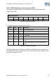
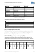
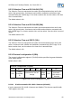
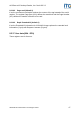
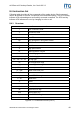
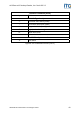
Table Of Contents
- Safety Instructions / Warning - Read before start-up!
- Preface
- 1 Scope
- 2 Extended Documentation
- 3 Definitions and Abbreviations
- 4 Supported tags
- 5 The mifare® Transponder Family
- 6 ISO 14443 Type B
- 7 Hardware
- 8 Software for contactless interface functions
- 8.1 ASCII Protocol
- 8.2 Binary Protocol
- 8.3 Register Set
- 8.3.1 EEPROM memory organization
- 8.3.2 Unique device ID (00h – 04h)
- 8.3.3 Station ID (0Ah)
- 8.3.4 Protocol configuration (0Bh)
- 8.3.5 BAUD, Baud rate control register (0Ch)
- 8.3.6 Command Guard Time (0Dh)
- 8.3.7 OPMODE, operating mode register (0Eh)
- 8.3.8 Single Shot Time-out (0Fh)
- 8.3.9 Protocol configuration 2 (13h)
- 8.3.9.1 Disable multi-tag reset (default 0)
- 8.3.9.2 Disable start-up message (default 0)
- 8.3.9.3 Enable binary frame v2 (default 0)
- 8.3.9.4 Noisy Environment (default 0)
- 8.3.9.5 Reset Recovery Time Multiplier (default 0)
- 8.3.9.6 Enable ISO14443 B Anti-collision (default 0)
- 8.3.9.7 Disable ISO 14443-4 Error Handling (default 0)
- 8.3.10 Reset Off Time (14h)
- 8.3.11 Reset Recovery Time (15h)
- 8.3.12 Application Family Identifier (16h)
- 8.3.13 Selection Time-out ISO 14443A (17h)
- 8.3.14 Selection Time-out ISO 14443B (18h)
- 8.3.15 Selection Time-out SR176 (19h)
- 8.3.16 Protocol configuration 3 (1Bh)
- 8.3.17 User data (80h - EFh)
- 8.4 Instruction Set
- 8.4.1 Overview
- 8.4.2 Error Codes
- 8.4.3 Common commands
- 8.4.3.1 Test Continuous Read
- 8.4.3.2 Continuous Read
- 8.4.3.3 Set LED
- 8.4.3.4 DES encryption / decryption of data
- 8.4.3.5 Get ID
- 8.4.3.6 Multi-Tag Selection / List
- 8.4.3.7 Include tag type
- 8.4.3.8 Exclude tag type
- 8.4.3.9 Set tag type
- 8.4.3.10 Set Configuration Flags
- 8.4.3.11 Set Configuration Register
- 8.4.3.12 Antenna power on/off
- 8.4.3.13 Read/Write user port
- 8.4.3.14 Quiet
- 8.4.3.15 Read block
- 8.4.3.16 Read reader EEPROM
- 8.4.3.17 Select
- 8.4.3.18 Get Version
- 8.4.3.19 Write DESFire key
- 8.4.3.20 Write master key
- 8.4.3.21 Write block
- 8.4.3.22 Write EEPROM
- 8.4.3.23 Reset
- 8.4.3.24 Field Reset
- 8.4.4 ISO 14443 Type A only commands
- 8.4.5 SR176 only commands
- 8.4.6 DESFire command set
- 8.4.6.1 Authenticate
- 8.4.6.2 Change Key Settings
- 8.4.6.3 Get Key Settings
- 8.4.6.4 Change Key
- 8.4.6.5 Get Key Version
- 8.4.6.6 Create Application
- 8.4.6.7 Delete Application
- 8.4.6.8 Get Application IDs
- 8.4.6.9 Select Application
- 8.4.6.10 Format PICC
- 8.4.6.11 Get Version
- 8.4.6.12 Get File IDs
- 8.4.6.13 Get File Settings
- 8.4.6.14 Select File
- 8.4.6.15 Change File Settings
- 8.4.6.16 Create Standard Data File
- 8.4.6.17 Create Backup Data File
- 8.4.6.18 Create Value File
- 8.4.6.19 Create Linear Record File
- 8.4.6.20 Create Cyclic Record File
- 8.4.6.21 Delete File
- 8.4.6.22 Read Data / Records
- 8.4.6.23 Data files
- 8.4.6.24 Record file
- 8.4.6.25 Write Data / Record
- 8.4.6.26 Get Value
- 8.4.6.27 Credit
- 8.4.6.28 Debit
- 8.4.6.29 Limited Credit
- 8.4.6.30 Clear Record File
- 8.4.6.31 Commit Transaction
- 8.4.6.32 Abort Transaction
- 9 Software for contact interface functions
- 10 Frequently Asked Questions
- 11 References
- 12 Appendix A: SAM
- 13 Appendix C: Timings
- 14 Appendix D: Release Notes
- 15 Appendix F: Approvals / Certificates

ACGPass e-ID Desktop Reader, Ver. Dual ISO 2.3
The following table describes the exact baud rates used by the reader.
Baud rate Exact baud rate Difference
9600 baud 9576 baud -0.25 %
19200 baud 19261 baud 0.32 %
38400 baud 38523 baud 0.32 %
57600 baud 58448 baud 1.47 %
115200 baud 113000 baud -1.91 %
230400 baud 241545 baud 4.84 %
460800 baud 483091 baud 4.84 %
Figure 8-11: Exact baud rates
The following table describes the communication settings
Description
8 data bits
No parity bit
1 stop bit
No flow control
Figure 8-12: Communication settings
8.3.6 Command Guard Time (0Dh)
The Command Guard Time is used to ensure that commands are not sent to fast
consecutively. Following commands are sent after the guard time is elapsed. One
time slice is around 37,8us. The longest timeout value is 9,6ms (FFh).
The default value is 20h (1,2ms).
8.3.7 OPMODE, operating mode register (0Eh)
The operation mode register defines which tag types the reader supports. This
register enables fast tag recognition because only defined tag types are requested.
Operation mode register
Bit 7
(MSB)
Bit 6 Bit 5 Bit 4 Bit 3 Bit 2 Bit 1 Bit 0
(LSB)
RFU
RFU
RFU
RFU
RFU
SR176
ISO
14443B
ISO
14443A
Figure 8-13: Operation mode register
ASSA ABLOY Identification Technologies GmbH 43