
User's Manual
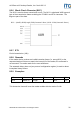
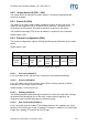
Table Of Contents
- Safety Instructions / Warning - Read before start-up!
- Preface
- 1 Scope
- 2 Extended Documentation
- 3 Definitions and Abbreviations
- 4 Supported tags
- 5 The mifare® Transponder Family
- 6 ISO 14443 Type B
- 7 Hardware
- 8 Software for contactless interface functions
- 8.1 ASCII Protocol
- 8.2 Binary Protocol
- 8.3 Register Set
- 8.3.1 EEPROM memory organization
- 8.3.2 Unique device ID (00h – 04h)
- 8.3.3 Station ID (0Ah)
- 8.3.4 Protocol configuration (0Bh)
- 8.3.5 BAUD, Baud rate control register (0Ch)
- 8.3.6 Command Guard Time (0Dh)
- 8.3.7 OPMODE, operating mode register (0Eh)
- 8.3.8 Single Shot Time-out (0Fh)
- 8.3.9 Protocol configuration 2 (13h)
- 8.3.9.1 Disable multi-tag reset (default 0)
- 8.3.9.2 Disable start-up message (default 0)
- 8.3.9.3 Enable binary frame v2 (default 0)
- 8.3.9.4 Noisy Environment (default 0)
- 8.3.9.5 Reset Recovery Time Multiplier (default 0)
- 8.3.9.6 Enable ISO14443 B Anti-collision (default 0)
- 8.3.9.7 Disable ISO 14443-4 Error Handling (default 0)
- 8.3.10 Reset Off Time (14h)
- 8.3.11 Reset Recovery Time (15h)
- 8.3.12 Application Family Identifier (16h)
- 8.3.13 Selection Time-out ISO 14443A (17h)
- 8.3.14 Selection Time-out ISO 14443B (18h)
- 8.3.15 Selection Time-out SR176 (19h)
- 8.3.16 Protocol configuration 3 (1Bh)
- 8.3.17 User data (80h - EFh)
- 8.4 Instruction Set
- 8.4.1 Overview
- 8.4.2 Error Codes
- 8.4.3 Common commands
- 8.4.3.1 Test Continuous Read
- 8.4.3.2 Continuous Read
- 8.4.3.3 Set LED
- 8.4.3.4 DES encryption / decryption of data
- 8.4.3.5 Get ID
- 8.4.3.6 Multi-Tag Selection / List
- 8.4.3.7 Include tag type
- 8.4.3.8 Exclude tag type
- 8.4.3.9 Set tag type
- 8.4.3.10 Set Configuration Flags
- 8.4.3.11 Set Configuration Register
- 8.4.3.12 Antenna power on/off
- 8.4.3.13 Read/Write user port
- 8.4.3.14 Quiet
- 8.4.3.15 Read block
- 8.4.3.16 Read reader EEPROM
- 8.4.3.17 Select
- 8.4.3.18 Get Version
- 8.4.3.19 Write DESFire key
- 8.4.3.20 Write master key
- 8.4.3.21 Write block
- 8.4.3.22 Write EEPROM
- 8.4.3.23 Reset
- 8.4.3.24 Field Reset
- 8.4.4 ISO 14443 Type A only commands
- 8.4.5 SR176 only commands
- 8.4.6 DESFire command set
- 8.4.6.1 Authenticate
- 8.4.6.2 Change Key Settings
- 8.4.6.3 Get Key Settings
- 8.4.6.4 Change Key
- 8.4.6.5 Get Key Version
- 8.4.6.6 Create Application
- 8.4.6.7 Delete Application
- 8.4.6.8 Get Application IDs
- 8.4.6.9 Select Application
- 8.4.6.10 Format PICC
- 8.4.6.11 Get Version
- 8.4.6.12 Get File IDs
- 8.4.6.13 Get File Settings
- 8.4.6.14 Select File
- 8.4.6.15 Change File Settings
- 8.4.6.16 Create Standard Data File
- 8.4.6.17 Create Backup Data File
- 8.4.6.18 Create Value File
- 8.4.6.19 Create Linear Record File
- 8.4.6.20 Create Cyclic Record File
- 8.4.6.21 Delete File
- 8.4.6.22 Read Data / Records
- 8.4.6.23 Data files
- 8.4.6.24 Record file
- 8.4.6.25 Write Data / Record
- 8.4.6.26 Get Value
- 8.4.6.27 Credit
- 8.4.6.28 Debit
- 8.4.6.29 Limited Credit
- 8.4.6.30 Clear Record File
- 8.4.6.31 Commit Transaction
- 8.4.6.32 Abort Transaction
- 9 Software for contact interface functions
- 10 Frequently Asked Questions
- 11 References
- 12 Appendix A: SAM
- 13 Appendix C: Timings
- 14 Appendix D: Release Notes
- 15 Appendix F: Approvals / Certificates

ACGPass e-ID Desktop Reader, Ver. Dual ISO 2.3
8.3.2 Unique device ID (00h – 04h)
The unique device ID identifies a reader module. It is factory programmed and
cannot be changed.
8.3.3 Station ID (0Ah)
The station ID is used in binary mode to address a device in party line set up. The
station ID can range from 01h to FEh and can be set freely. The value 00h is
reserved for the bus master. All readers send their response to this device.
The broadcast message (FFh) forces all readers to response to the command.
Default value is 01h.
8.3.4 Protocol configuration (0Bh)
The protocol configuration register (PCON) specifies general behavior of the reader
device.
Default value is 41h.
Protocol configuration register
Bit 7 Bit 6 Bit 5 Bit 4 Bit 3 Bit 2 Bit 1 Bit 0
Extend-
ed ID
Extend-
ed
Protocol
Single-
shot
LED
New
serial
mode
Multitag Protocol
Auto-
start
Figure 8-5: Protocol configuration register
8.3.4.1 Auto start (default 1)
If set, the reader device will start up in continuous read mode automatically.
8.3.4.2 Protocol (default 0)
If set, the reader uses binary protocol mode. Refer to binary protocol for further
information on the binary protocol format.
Default setting = ASCII protocol (0).
8.3.4.3 Multitag (default 0)
The Multitag flag will enable multi-tag recognition in continuous read mode. All tags
are detected and displayed. Due to the more complex search algorithm, the
continuous read command decreases its detection speed.
8.3.4.4 New serial mode (default 0)
If set, new serial mode is enabled. The leading character ‘M’ is added to the serial
number of ISO 14443 type A tags, a leading 'Z' character is added to ISO 14443 type
B tags and a leading 'S' character for SR176 tags.
ASSA ABLOY Identification Technologies GmbH 39