
User's Manual

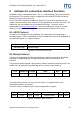
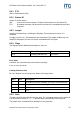
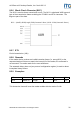

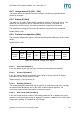
Table Of Contents
- Safety Instructions / Warning - Read before start-up!
- Preface
- 1 Scope
- 2 Extended Documentation
- 3 Definitions and Abbreviations
- 4 Supported tags
- 5 The mifare® Transponder Family
- 6 ISO 14443 Type B
- 7 Hardware
- 8 Software for contactless interface functions
- 8.1 ASCII Protocol
- 8.2 Binary Protocol
- 8.3 Register Set
- 8.3.1 EEPROM memory organization
- 8.3.2 Unique device ID (00h – 04h)
- 8.3.3 Station ID (0Ah)
- 8.3.4 Protocol configuration (0Bh)
- 8.3.5 BAUD, Baud rate control register (0Ch)
- 8.3.6 Command Guard Time (0Dh)
- 8.3.7 OPMODE, operating mode register (0Eh)
- 8.3.8 Single Shot Time-out (0Fh)
- 8.3.9 Protocol configuration 2 (13h)
- 8.3.9.1 Disable multi-tag reset (default 0)
- 8.3.9.2 Disable start-up message (default 0)
- 8.3.9.3 Enable binary frame v2 (default 0)
- 8.3.9.4 Noisy Environment (default 0)
- 8.3.9.5 Reset Recovery Time Multiplier (default 0)
- 8.3.9.6 Enable ISO14443 B Anti-collision (default 0)
- 8.3.9.7 Disable ISO 14443-4 Error Handling (default 0)
- 8.3.10 Reset Off Time (14h)
- 8.3.11 Reset Recovery Time (15h)
- 8.3.12 Application Family Identifier (16h)
- 8.3.13 Selection Time-out ISO 14443A (17h)
- 8.3.14 Selection Time-out ISO 14443B (18h)
- 8.3.15 Selection Time-out SR176 (19h)
- 8.3.16 Protocol configuration 3 (1Bh)
- 8.3.17 User data (80h - EFh)
- 8.4 Instruction Set
- 8.4.1 Overview
- 8.4.2 Error Codes
- 8.4.3 Common commands
- 8.4.3.1 Test Continuous Read
- 8.4.3.2 Continuous Read
- 8.4.3.3 Set LED
- 8.4.3.4 DES encryption / decryption of data
- 8.4.3.5 Get ID
- 8.4.3.6 Multi-Tag Selection / List
- 8.4.3.7 Include tag type
- 8.4.3.8 Exclude tag type
- 8.4.3.9 Set tag type
- 8.4.3.10 Set Configuration Flags
- 8.4.3.11 Set Configuration Register
- 8.4.3.12 Antenna power on/off
- 8.4.3.13 Read/Write user port
- 8.4.3.14 Quiet
- 8.4.3.15 Read block
- 8.4.3.16 Read reader EEPROM
- 8.4.3.17 Select
- 8.4.3.18 Get Version
- 8.4.3.19 Write DESFire key
- 8.4.3.20 Write master key
- 8.4.3.21 Write block
- 8.4.3.22 Write EEPROM
- 8.4.3.23 Reset
- 8.4.3.24 Field Reset
- 8.4.4 ISO 14443 Type A only commands
- 8.4.5 SR176 only commands
- 8.4.6 DESFire command set
- 8.4.6.1 Authenticate
- 8.4.6.2 Change Key Settings
- 8.4.6.3 Get Key Settings
- 8.4.6.4 Change Key
- 8.4.6.5 Get Key Version
- 8.4.6.6 Create Application
- 8.4.6.7 Delete Application
- 8.4.6.8 Get Application IDs
- 8.4.6.9 Select Application
- 8.4.6.10 Format PICC
- 8.4.6.11 Get Version
- 8.4.6.12 Get File IDs
- 8.4.6.13 Get File Settings
- 8.4.6.14 Select File
- 8.4.6.15 Change File Settings
- 8.4.6.16 Create Standard Data File
- 8.4.6.17 Create Backup Data File
- 8.4.6.18 Create Value File
- 8.4.6.19 Create Linear Record File
- 8.4.6.20 Create Cyclic Record File
- 8.4.6.21 Delete File
- 8.4.6.22 Read Data / Records
- 8.4.6.23 Data files
- 8.4.6.24 Record file
- 8.4.6.25 Write Data / Record
- 8.4.6.26 Get Value
- 8.4.6.27 Credit
- 8.4.6.28 Debit
- 8.4.6.29 Limited Credit
- 8.4.6.30 Clear Record File
- 8.4.6.31 Commit Transaction
- 8.4.6.32 Abort Transaction
- 9 Software for contact interface functions
- 10 Frequently Asked Questions
- 11 References
- 12 Appendix A: SAM
- 13 Appendix C: Timings
- 14 Appendix D: Release Notes
- 15 Appendix F: Approvals / Certificates

ACGPass e-ID Desktop Reader, Ver. Dual ISO 2.3
8 Software for contactless interface functions
By default, data is transmitted at 9600, n, 8, 1, no handshaking. Two protocol modes
are supported. The protocol mode is configured in the reader EEPROM. As factory
default, the ASCII protocol is used.
If the PC/SC driver has been installed on the host PC, then the commands of this
chapter can’t be used as such. Only the PC/SC specification is valid in this case. The
reader also can be installed with the standard USB driver. The driver can be
downloaded from http://www.aaitg.com. This driver enables the usage of a virtual
COM port on the host PC. Then all commands mentioned below can be used.
8.1 ASCII Protocol
This protocol is designed for easy handling. The commands are issued using a
terminal program. Data is transmitted as ASCII hexadecimal that can be displayed on
any terminal program (i.e. HyperTerminal).
Command Data
Variable length Variable length
Figure 8-1: ASCII protocol frame
8.2 Binary Protocol
This protocol is designed for industrial applications with synchronization and frame
checking. An addressing byte for party line (master/slave, multi-drop) is also
included.
The protocol usually requires a device driver. Data is transmitted in binary mode. The
reader uses an internal binary watchdog timer to ensure correct framing.
STX Station ID Length Data BCC ETX
1 byte 1 byte 1 byte Variable length 1 byte 1 byte
Figure 8-2: Binary Frame Version 1
The binary frame version 2 is only sent to the host. It is implemented to give
extended information to the host.
Version 2 must be enabled in the Protocol configuration 2 register.
STX Station ID Length Flags Data BCC ETX
1 byte 1 byte 1 byte 1 byte Variable length 1 byte 1 byte
Figure 8-3: Binary Frame Version 2
ASSA ABLOY Identification Technologies GmbH 34