
User's Manual
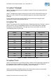
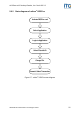
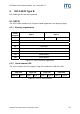
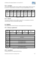
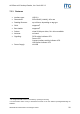
Table Of Contents
- Safety Instructions / Warning - Read before start-up!
- Preface
- 1 Scope
- 2 Extended Documentation
- 3 Definitions and Abbreviations
- 4 Supported tags
- 5 The mifare® Transponder Family
- 6 ISO 14443 Type B
- 7 Hardware
- 8 Software for contactless interface functions
- 8.1 ASCII Protocol
- 8.2 Binary Protocol
- 8.3 Register Set
- 8.3.1 EEPROM memory organization
- 8.3.2 Unique device ID (00h – 04h)
- 8.3.3 Station ID (0Ah)
- 8.3.4 Protocol configuration (0Bh)
- 8.3.5 BAUD, Baud rate control register (0Ch)
- 8.3.6 Command Guard Time (0Dh)
- 8.3.7 OPMODE, operating mode register (0Eh)
- 8.3.8 Single Shot Time-out (0Fh)
- 8.3.9 Protocol configuration 2 (13h)
- 8.3.9.1 Disable multi-tag reset (default 0)
- 8.3.9.2 Disable start-up message (default 0)
- 8.3.9.3 Enable binary frame v2 (default 0)
- 8.3.9.4 Noisy Environment (default 0)
- 8.3.9.5 Reset Recovery Time Multiplier (default 0)
- 8.3.9.6 Enable ISO14443 B Anti-collision (default 0)
- 8.3.9.7 Disable ISO 14443-4 Error Handling (default 0)
- 8.3.10 Reset Off Time (14h)
- 8.3.11 Reset Recovery Time (15h)
- 8.3.12 Application Family Identifier (16h)
- 8.3.13 Selection Time-out ISO 14443A (17h)
- 8.3.14 Selection Time-out ISO 14443B (18h)
- 8.3.15 Selection Time-out SR176 (19h)
- 8.3.16 Protocol configuration 3 (1Bh)
- 8.3.17 User data (80h - EFh)
- 8.4 Instruction Set
- 8.4.1 Overview
- 8.4.2 Error Codes
- 8.4.3 Common commands
- 8.4.3.1 Test Continuous Read
- 8.4.3.2 Continuous Read
- 8.4.3.3 Set LED
- 8.4.3.4 DES encryption / decryption of data
- 8.4.3.5 Get ID
- 8.4.3.6 Multi-Tag Selection / List
- 8.4.3.7 Include tag type
- 8.4.3.8 Exclude tag type
- 8.4.3.9 Set tag type
- 8.4.3.10 Set Configuration Flags
- 8.4.3.11 Set Configuration Register
- 8.4.3.12 Antenna power on/off
- 8.4.3.13 Read/Write user port
- 8.4.3.14 Quiet
- 8.4.3.15 Read block
- 8.4.3.16 Read reader EEPROM
- 8.4.3.17 Select
- 8.4.3.18 Get Version
- 8.4.3.19 Write DESFire key
- 8.4.3.20 Write master key
- 8.4.3.21 Write block
- 8.4.3.22 Write EEPROM
- 8.4.3.23 Reset
- 8.4.3.24 Field Reset
- 8.4.4 ISO 14443 Type A only commands
- 8.4.5 SR176 only commands
- 8.4.6 DESFire command set
- 8.4.6.1 Authenticate
- 8.4.6.2 Change Key Settings
- 8.4.6.3 Get Key Settings
- 8.4.6.4 Change Key
- 8.4.6.5 Get Key Version
- 8.4.6.6 Create Application
- 8.4.6.7 Delete Application
- 8.4.6.8 Get Application IDs
- 8.4.6.9 Select Application
- 8.4.6.10 Format PICC
- 8.4.6.11 Get Version
- 8.4.6.12 Get File IDs
- 8.4.6.13 Get File Settings
- 8.4.6.14 Select File
- 8.4.6.15 Change File Settings
- 8.4.6.16 Create Standard Data File
- 8.4.6.17 Create Backup Data File
- 8.4.6.18 Create Value File
- 8.4.6.19 Create Linear Record File
- 8.4.6.20 Create Cyclic Record File
- 8.4.6.21 Delete File
- 8.4.6.22 Read Data / Records
- 8.4.6.23 Data files
- 8.4.6.24 Record file
- 8.4.6.25 Write Data / Record
- 8.4.6.26 Get Value
- 8.4.6.27 Credit
- 8.4.6.28 Debit
- 8.4.6.29 Limited Credit
- 8.4.6.30 Clear Record File
- 8.4.6.31 Commit Transaction
- 8.4.6.32 Abort Transaction
- 9 Software for contact interface functions
- 10 Frequently Asked Questions
- 11 References
- 12 Appendix A: SAM
- 13 Appendix C: Timings
- 14 Appendix D: Release Notes
- 15 Appendix F: Approvals / Certificates

ACGPass e-ID Desktop Reader, Ver. Dual ISO 2.3
6.1.3 Lock byte
The lock byte defines the write access condition of a pair of pages. Each bit can only
be set once. This procedure is irreversible. This byte is implemented as an OTP.
Bit 7 Bit 6 Bit 5 Bit 4 Bit 3 Bit 2 Bit 1 Bit 0
Page 0Eh
Page 0Fh
Page 0Ch
Page 0Dh
Page 0Ah
Page 0Bh
Page 08h
Page 09h
Page 06h
Page 07h
Page 04h
Page 05h
Page 02h
Page 03h
Page 00h
Page 01h
Figure 6-3: Lock byte
6.1.4 Chip ID
The Chip ID is defined in the low nibble of page 0Fh. It is manufacturer set and is
used internally to select and separate single tags.
6.2 SRIX4K
The SRIX4K label contains 512 bytes of data organized into four-byte pages.
6.2.1 Memory organization
Block
address
Byte 3 Byte 2 Byte 1 Byte 0
FFh OTP Lock Reg ST Reserved ST Reserved Fixed Chip ID
7Fh User data
… …
07h User data
06h 32 bits binary counter
05h 32 bits binary counter
04h 32 bits Boolean Area
03h 32 bits Boolean Area
02h 32 bits Boolean Area
01h 32 bits Boolean Area
00h 32 bits Boolean Area
Figure 6-4: SRIX4K memory organization
6.2.2 Lock block
Locking of blocks is not supported with this tag.
ASSA ABLOY Identification Technologies GmbH 25