
User's Manual

HF Mifare Easy Module V1.0
ACG Identification Technologies GmbH 20
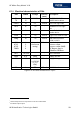
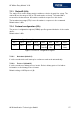
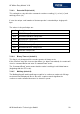
6.1.2 Electrical characteristics of PINs
PIN PIN Nr Voltage Current
(max)
Description
RX
TX
11
12
USART
1
- To RS232, RS485 or
RS422 device driver
USER 14 TTL
2
25 mA User sets logic state
RES 15 TTL - Hardware reset if logic
low
EN 16 TTL - Low will disable the
reader device
LEDr 17 TTL 25 mA Logic Low, used for LED
LEDg 18 TTL 25 mA
With 330 Ω (internal
serial) resistor
ARX
ATX1
ATX2
TGND
1
2
5
6
(depends
on antenna
tuning)
200 mA
PP
Antenna input
Antenna output
Antenna output (GND)
RF-Output: approx
150mW at 50 Ohms
RFU 7,8,9,10 - - Not connected
GND 4,19 GND - Supply Ground
VDD 3,20 +5 V DC
(+4.5V DC
to +5.5
VDC)
150 mA Supply Voltage
DIR 13 TTL 25 mA RS485 direction
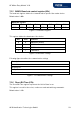
Figure 6-2: Electrical characteristics of pins
1
Universal Synchronous Asynchronous Receiver Transmitter
2
TTL buffer output / input