
User's Manual Part 1


13,56 MHz Multitag Reader Module, Version 0.9v
ACG Identification Technologies AT Page 5
3 Tag organization
3.1 State diagram
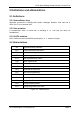
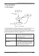
Figure 3-1: State Diagram
The state diagram shows the different states of a tag. First the tag must be power up.
Next command initialize a tag using the anticollision or inventory command.
A selection of a tag is necessary to interact with a tag of interest especially if more
than one tag is present at the same time. Only selected tags are capable to response
to higher commands such as read or write page data.
READY state A tag enters the READY state after it receives a
valid inventory or anticollision command. At this
state the tag all serial numbers are known and
the tag is ready to select.
ACTIVE state After a selection the tag is in the ACTIVE state.
Only an activated tag can respond to a read or
write command.
HALT state The HALT command disables a tag for further
communication. The tag is still in the field but
dies not respond to any command. To activate a
tag and to put it back to the Ready state a
WAKE-UP command has to be used.
Power off
Ready
A
CTIVE
HALT
Anticollision Loop,
Inventor
y
WAKE-UP
Application
Select