
User's Manual Part 1

13,56 MHz Multitag Reader Module, Version 0.9v
ACG Identification Technologies AT Page 15
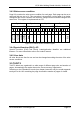
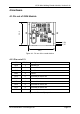
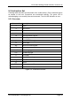
4.1.2 Pin out of J2
PIN PIN Nr Description
VDD 20 +5 V DC
GND 19 Ground
LEDg 18 LED green (reading LED)
LEDr 17 LED red
EN 16 Enable reader, open or logic high
RFU 15 Reserved for future use
USER 14 User Port
DIR 13 Direction of RS 485
TX 12 TX to PC
RX 11 RX from PC
Figure 4-3: Pin out of jumper 2
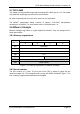
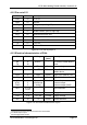
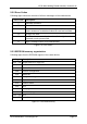
4.1.3 Electrical characteristics of PINs
PIN PIN Nr Voltage Current
(max)
Description
RX
TX
11
12
USART
2
- To RS232, RS485 device
driver
USER 14 TTL
3
25 mA User sets logic state
EN 16 ST
4
25 mA Low will disable the
reader device
LEDr 17 GND 25 mA Logic Low, used for LED
LEDg 18 LED 25 mA
With 330 Ω (internal)
ARX
ATX1
TGND
1
2
6
(depends
on antenna
tuning)
200 mA
PP
Antenna input
Antenna output
Antenna output (GND)
RFU 5,7,8,9,
10,15
- - Not connected
GND 4,19 GND - Supply Ground
VDD 3,20 +5 V DC 150 mA Supply Voltage
DIR 13 TTL 25 mA RS485 direction
Figure 4-4: Electrical characteristics of pins
2
Universal Synchronous Asynchronous Receiver Transmitter
3
TTL buffer output / input
4
Schmitt trigger buffer output