
User's Manual Part 1

13,56 MHz Multitag Reader Module, Version 0.9v
ACG Identification Technologies AT Page 11
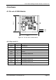
3.6 SR176
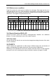
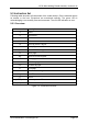
The SR176 label contains only 64 bytes of data organized in two bytes per page.
3.6.1 Memory organization
Page
address
Byte 1 Byte 0
0Fh Lock byte RFU Chip ID
0Eh User data
… …
04h User data
03h Serial number
02h Serial number
01h Serial number
00h Serial number
Figure 3-11: SR176 memory organization
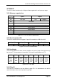
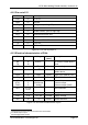
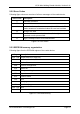
3.6.2 Serial number UID
The UID is stored at the first 4 pages. Page 00h contains the LSB of the UID.
Page 03h Page 02h Page 01h Page 00h
Byte 1h Byte 0 Byte 1 Byte 0 Byte 1 Byte 0 Byte 1 Byte 0
Figure 3-12: SR176 Serial number
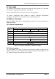
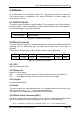
3.6.3 Lock byte
The lock byte defines the write access condition of a pair of pages. Each bit can only
be set once. This procedure is irreversible. This byte is implemented as OTP.
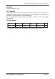
Bit 7 Bit 6 Bit 5 Bit 4 Bit 3 Bit 2 Bit 1 Bit 0
Page 0Eh
Page 0Fh
Page 0Ch
Page 0Dh
Page 0Ah
Page 0Bh
Page 08h
Page 09h
Page 06h
Page 07h
Page 04h
Page 05h
Page 02h
Page 03h
Page 00h
Page 01h
Figure 3-13: Lock byte
3.6.4 Chip ID
The Chip ID is defined in the low nibble of page 0Fh. It is manufacturer set and is
used internally to select and separate single tags.