X58 Deluxe User Manual Version 1.1 Published April 2009 Copyright©2009 ASRock INC. All rights reserved.
Copyright Notice: No part of this manual may be reproduced, transcribed, transmitted, or translated in any language, in any form or by any means, except duplication of documentation by the purchaser for backup purpose, without written consent of ASRock Inc. Products and corporate names appearing in this manual may or may not be registered trademarks or copyrights of their respective companies, and are used only for identification or explanation and to the owners’ benefit, without intent to infringe.
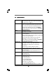
Contents 1 Introduction ................................................... 5 1.1 1.2 1.3 1.4 1.5 1.6 1.7 1.8 1.9 Package Contents .......................................................... Specifications ................................................................. Two SLITM Graphics Card Support List ............................ Three SLITM Graphics Card Support List ......................... Two CrossFireXTM Graphics Card Support List ................ Three CrossFireXTM Graphics Card Support List ..
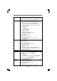
2.19 Installing Windows® XP / XP 64-bit / VistaTM / VistaTM 64-bit Without RAID Functions ................................................. 49 2.19.1 Installing Windows® XP / XP 64-bit Without RAID Functions ............................................................ 49 2.19.2 Installing Windows® VistaTM / VistaTM 64-bit Without RAID Functions ................................................... 50 2.20 Untied Overclocking Technology ................................... 50 3 BIOS SSETUP ETUP UTILITY .......
Chapter 1: Introduction Thank you for purchasing ASRock X58 Deluxe motherboard, a reliable motherboard produced under ASRock’s consistently stringent quality control. It delivers excellent performance with robust design conforming to ASRock’s commitment to quality and endurance. In this manual, chapter 1 and 2 contain introduction of the motherboard and step-by-step guide to the hardware installation. Chapter 3 and 4 contain the configuration guide to BIOS setup and information of the Support CD.
1.2 Specifications Platform CPU Chipset Memory Expansion Slot Audio LAN Rear Panel I/O - ATX Form Factor: 12.0-in x 9.6-in, 30.5 cm x 24.
Connector - 1 x IEEE 1394 Port - HD Audio Jack: Side Speaker/Rear Speaker/Central/Bass/ Line in/Front Speaker/Microphone (see CAUTION 5) - 6 x SATAII 3.0Gb/s connectors, support RAID (RAID 0, RAID 1, RAID 10, RAID 5 and Intel Matrix Storage), NCQ, AHCI and “Hot Plug” functions (see CAUTION 6) * 2 SATAII 3.
OS Certifications - Microsoft® Windows® XP / XP 64-bit / VistaTM / VistaTM 64-bit compliant - FCC, CE, WHQL * For detailed product information, please visit our website: http://www.asrock.com WARNING Please realize that there is a certain risk involved with overclocking, including adjusting the setting in the BIOS, applying Untied Overclocking Technology, or using the thirdparty overclocking tools.
. Featuring an advanced proprietary hardware and software design, Intelligent Energy Saver is a revolutionary technology that delivers unparalleled power savings. In other words, it is able to provide exceptional power saving and improve power efficiency without sacrificing computing performance. Please visit our website for the operation procedures of Intelligent Energy Saver. ASRock website: http://www.asrock.com 10.
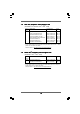
1.3 Two SLI TM Graphics Card Suppor Supportt List (for Windows® XP / XP 64-bit / VistaTM / VistaTM 64-bit) Chipset Model Name Chipset Name Driver Gigabyte GV-NX88T256H GeForce 8800 GT 180.48 Gigabyte GV-NX88S512H-B LEADTEK PX8800 GTX TDH GeForce 8800 GTS GeForce 8800 GTX 180.48 180.48 Chaintech GES96GT-A1512P ASUS EN9800GT TDP/HTDP/512M GeForce 9600 GT GeForce 9800GT 180.48 180.48 LEADTEK PX9800GTX LEADTEK PX9800 GTX+ GeForce 9800GTX GeForce 9800GTX+ 180.48 180.
1.5 Two CrossF ireX TM Graphics Card Suppor CrossFireX Supportt List (for Windows® VistaTM / VistaTM 64-bit) Chipset Model Name Chipset Name Driver Vendor ATI MSI RX2600PRO-T2D256EZ Radeon HD 2600PRO Catalyst 8.9 Gigabyte GV-RX26T256HP-B Powercolor AX3650 512MMD3-XP Radeon HD 2600XT RADEON 3650 Catalyst 8.9 Catalyst 8.9 Gigabyte GV-RX385256H-B Powercolor AX3870 512MD4-H RADEON 3850 RADEON 3870 Catalyst 8.9 Catalyst 8.
1.8 Motherboard Layout 1 3 2 24.4cm (9.6 in) 4 PS2 Mouse PS2 Keyboard 1 30.5cm (12.0 in) ATXPWR1 RESET PANEL1 PLED PWRBTN 1 HDLED FRONT_1394 DDR3_C2 (64 bit, 240-pin module) 1 USB8_9 1 DDR3_C1 (64 bit, 240-pin module) DDR3_B1 (64 bit, 240-pin module) DDR3_A1 (64 bit, 240-pin module) 3 Channels DDR3 QPI 6.4GT/s CHA_FAN2 NB_FAN1 CHA_FAN1 PWR_FAN1 LAN PHY PCIE1 RoHS 32 AUDIO CODEC 8 9 10 11 12 13 PCI1 3-WaySLI CD1 PCIE2 VIA VT6330 PCI Express 2.
1.9 I/O PPanel anel 1 16 1 2 3 *4 5 6 7 8 3 2 14 15 13 PS/2 Mouse Port (Green) Coaxial SPDIF Out Port IEEE 1394 Port LAN RJ-45 Port Side Speaker (Gray) Rear Speaker (Black) Central / Bass (Orange) Line In (Light Blue) 4 12 ** 9 10 11 12 13 14 15 16 5 8 6 7 9 10 11 Front Speaker (Lime) Microphone (Pink) USB 2.0 Ports (USB45) USB 2.0 Ports (USB23) USB 2.
Chapter 2: Installation This is an ATX form factor (12.0" x 9.6", 30.5 x 24.4 cm) motherboard. Before you install the motherboard, study the configuration of your chassis to ensure that the motherboard fits into it. Make sure to unplug the power cord before installing or removing the motherboard. Failure to do so may cause physical injuries to you and damages to motherboard components. 2.1 Screw Holes Place screws into the holes indicated by circles to secure the motherboard to the chassis.
2.3 CPU Installation For the installation of Intel 1366-Pin CPU, please follow the steps below. Load Plate Socket Body Contact Array Load Lever 1366-Pin Socket Overview Before you insert the 1366-Pin CPU into the socket, please check if the CPU surface is unclean or if there is any bent pin on the socket. Do not force to insert the CPU into the socket if above situation is found. Otherwise, the CPU will be seriously damaged. Step 1. Open the socket: Step 1-1.
Step 3-2. Orient the CPU with IHS (Integrated Heat Sink) up. Locate Pin1 and the two orientation key notches. orientation key notch alignment key Pin1 Pin1 alignment key orientation key notch 1366-Pin Socket 1366-Pin CPU For proper inserting, please ensure to match the two orientation key notches of the CPU with the two alignment keys of the socket. Step 3-3. Carefully place the CPU into the socket by using a purely vertical motion. Step 3-4.
2.4 Installation of CPU Fan and Heatsink This motherboard is equipped with 1366-Pin socket that supports Intel 1366-Pin CPU. Please adopt the type of heatsink and cooling fan compliant with Intel 1366-Pin CPU to dissipate heat. Before you installed the heatsink, you need to spray thermal interface material between the CPU and the heatsink to improve heat dissipation. Ensure that the CPU and the heatsink are securely fastened and in good contact with each other.
2.5 Installation of Memor y Modules (DIMM) This motherboard provides six 240-pin DDR3 (Double Data Rate 3) DIMM slots, and supports Triple Channel Memory Technology. For triple channel configuration, you always need to install identical (the same brand, speed, size and chip-type) DDR3 DIMM pair in the slots of the same color. In other words, you have to install identical DDR3 DIMM pair in Triple Channel (DDR3_A1, DDR3_B1 and DDR3_C1; White slots; see p.12 No.
Installing a DIMM Please make sure to disconnect power supply before adding or removing DIMMs or the system components. Step 1. Step 2. Unlock a DIMM slot by pressing the retaining clips outward. Align a DIMM on the slot such that the notch on the DIMM matches the break on the slot. notch break notch break The DIMM only fits in one correct orientation. It will cause permanent damage to the motherboard and the DIMM if you force the DIMM into the slot at incorrect orientation. Step 3.
2.6 Expansion Slots (PCI and PCI Express Slots) There are 3 PCI slots and 4 PCI Express slots on this motherboard. PCI slots: PCI slots are used to install expansion cards that have the 32-bit PCI interface. PCIE slots: PCIE1 / PCIE3 (PCIE x16 slot; Blue) is used for PCI Express x16 lane width graphics cards. PCIE2 / PCIE4 (PCIE x16 slot; Orange) is used for PCI Express x16 lane width graphics cards.
1. In single VGA card mode, it is recommended to install a PCI Express x16 graphics card on PCIE1 slot. 2. In CrossFireXTM mode or 2-Way SLITM mode, please install PCI Express x16 graphics cards on PCIE1 and PCIE3 slots. Therefore, both these two slots will work at x16 bandwidth. 3. In 3-Way SLITM mode, please install PCI Express x16 graphics cards on PCIE1, PCIE2 and PCIE3 slots. Therefore, PCIE3 slot will work at x16 bandwidth while PCIE1 and PCIE2 slots will work at x8 bandwidth. 4.
2.7 SLI TM, 3W ay SLI TM and Quad SLI TM Operation Guide 3-W This motherboard supports NVIDIA® SLITM, 3-Way SLITM and Quad SLITM (Scalable Link Interface) technology that allows you to install up to three identical PCI Express x16 graphics cards. Currently, NVIDIA® SLITM technology supports Windows® XP, XP 64-bit, VistaTM and VistaTM 64-bit OS. NVIDIA® 3-Way SLITM and Quad SLITM technology support Windows® VistaTM and VistaTM 64-bit OS only. Please follow the installation procedures in this section.
Step3. Align and insert ASRock SLI_Bridge_3S Card to the goldfingers on each graphics card. Make sure ASRock SLI_Bridge_3S Card is firmly in place. ASRock SLI_Bridge_3S Card Step4. Connect a VGA cable or a DVI cable to the monitor connector or the DVI connector of the graphics card that is inserted to PCIE1 slot.
2.7.1.2 Installing Three SLI TM -Ready Graphics Cards Step 1. Install the identical 3-Way SLITM-ready graphics cards that are NVIDIA® certified because different types of graphics cards will not work together properly. (Even the GPU chips version shall be the same.) Each graphics card should have two goldfingers for the 3-Way SLI Bridge connector. Insert one graphics card into PCIE1 slot, another graphics card to PCIE2 slot, and the other graphics card to PCIE3 slot.
2.7.2 Driver Installation and Setup Install the graphics card drivers to your system. After that, you can enable the MultiGraphics Processing Unit (GPU) feature in the NVIDIA® nView system tray utility. Please follow the below procedures to enable the multi-GPU feature. For Windows® XP / XP 64-bit OS: (For SLITM mode only) A. Double-click NVIDIA Settings icon on your Windows® taskbar. B. From the pop-up menu, select Set SLI and PhysX configuration. In Set PhysX GPU acceleration item, please select Enabled.
For Windows® VistaTM / VistaTM 64-bit OS: (For SLITM and Quad SLITM mode) A. Click the Start icon on your Windows taskbar. B. From the pop-up menu, select All Programs, and then click NVIDIA Corporation. C. Select NVIDIA Control Panel tab. D. Select Control Panel tab. E. From the pop-up menu, select Set SLI and PhysX configuration. In Set PhysX GPU acceleration item, please select Enabled. In Select an SLI configuration item, please select Enable SLI. And click Apply. F. Reboot your system. G.
For Windows® VistaTM / VistaTM 64-bit OS: (For 3-Way SLITM mode) A. Follow step A to D on page 26. B. From the pop-up menu, select Set SLI and PhysX configuration. In Select a hardware acceleration setting for PhysX item, please select Enabled. In Select an SLI configuration item, please select Enable 3-way SLI. And click Apply. C. Reboot your system. D. You can freely enjoy the benefit of 3-Way SLITM feature. * SLITM appearing here is a registered trademark of NVIDIA® Technologies Inc.
2.8 CrossFireX TM and Quad CrossFireX TM Operation Guide This motherboard supports CrossFireXTM and Quad CrossFireXTM feature. CrossFireXTM technology offers the most advantageous means available of combining multiple high performance Graphics Processing Units (GPU) in a single PC. Combining a range of different operating modes with intelligent software design and an innovative interconnect mechanism, CrossFireXTM enables the highest possible level of performance and image quality in any 3D application.
Step 2. Connect two Radeon graphics cards by installing ASRock XFire_Bridge_3S Card on ASRock XFire_Bridge_3S Card Interconnects on the top of Radeon graphics cards. (If there are two gold fingers on each Radeon graphics card, please use two ASRock XFire_Bridge_3S Cards to connect two Radeon graphics cards.) ASRock XFire_Bridge_3S Card Step 3. Connect the DVI monitor cable to the DVI connector on the Radeon graphics card on PCIE1 slot.
2.8.1.2 Installing Four CrossFireX TM-Ready Graphics Cards Step 1. Insert Radeon graphics cards into PCIE1, PCIE2, PCIE3 and PCIE4 slots. Make sure that the cards are properly seated on the slots. Step 2. Use one CrossFireXTM Bridge to connect Radeon graphics cards on PCIE1 and PCIE2 slots, use another CrossFireXTM Bridge to connect Radeon graphics cards on PCIE3 and PCIE4 slots, and use the other CrossFireXTM Bridge to connect Radeon graphics cards on PCIE2 and PCIE3 slots.
2.8.2 Driver Installation and Setup Step 1. Step 2. Power on your computer and boot into OS. Remove the ATITM driver if you have any VGA driver installed in your system. The Catalyst Uninstaller is an optional download. We recommend using this utility to uninstall any previously installed Catalyst drivers prior to installation. Please check AMD website for ATITM driver updates. Step 3. Step 4. Step 5. Install the required drivers to your system. For Windows® XP OS: A.
Although you have selected the option “Enable CrossFireTM”, the CrossFireXTM function may not work actually. Your computer will automatically reboot. After restarting your computer, please confirm whether the option “Enable CrossFireTM” in “ATI Catalyst Control Center” is selected or not; if not, please select it again, and then you are able to enjoy the benefit of CrossFireXTM feature. Step 7. Step 8. If you install four Radeon graphics cards, please install Hotfix.
2.9 Surround Display Feature This motherboard supports Surround Display upgrade. With the external add-on PCI Express VGA cards, you can easily enjoy the benefits of Surround Display feature. For the detailed instruction, please refer to the document at the following path in the Support CD: ..\ Surround Display Information 2.10 Jumpers Setup The illustration shows how jumpers are setup. When the jumper cap is placed on pins, the jumper is “Short”. If no jumper cap is placed on pins, the jumper is “Open”.
2.11 Onboard Headers and Connectors Onboard headers and connectors are NOT jumpers. Do NOT place jumper caps over these headers and connectors. Placing jumper caps over the headers and connectors will cause permanent damage of the motherboard! FDD connector (33-pin FLOPPY1) (see p.12 No. 27) Pin1 FLOPPY1 the red-striped side to Pin1 Note: Make sure the red-striped side of the cable is plugged into Pin1 side of the connector. Primary IDE connector (Blue) (39-pin IDE1, see p.12 No.
Serial ATA (SATA) Power Cable (Optional) connect to the SATA HDD power connector connect to the power supply USB 2.0 Headers USB_PWR P-9 P+9 GND DUMMY (9-pin USB8_9) (see p.12 No. 8) 1 GND P+8 P-8 USB_PWR USB_PWR P-7 P+7 GND DUMMY (9-pin USB6_7) (see p.12 No. 9) Please connect the black end of SATA power cable to the power connector on each drive. Then connect the white end of SATA power cable to the power connector of the power supply. Besides seven default USB 2.
1. High Definition Audio supports Jack Sensing, but the panel wire on the chassis must support HDA to function correctly. Please follow the instruction in our manual and chassis manual to install your system. 2. If you use AC’97 audio panel, please install it to the front panel audio header as below: A. Connect Mic_IN (MIC) to MIC2_L. B. Connect Audio_R (RIN) to OUT2_R and Audio_L (LIN) to OUT2_L. C. Connect Ground (GND) to Ground (GND). D. MIC_RET and OUT_RET are for HD audio panel only.
Chassis, NB and Power Fan Connectors (3-pin CHA_FAN1) (see p.12 No. 11) GND +12V CHA_FAN_SPEED (3-pin CHA_FAN2) (see p.12 No. 13) GND +12V CHA_FAN_SPEED (3-pin NB_FAN1) (see p.12 No. 12) GND +12V NB_FAN_SPEED (3-pin PWR_FAN1) (see p.12 No. 33) PWR_FAN_SPEED +12V GND CPU Fan Connector (4-pin CPU_FAN1) (see p.12 No. 35) Please connect the fan cables to the fan connectors and match the black wire to the ground pin.
Though this motherboard provides 8-pin ATX 12V power connector, it can still work if you adopt a traditional 4-pin ATX 12V power supply. To use the 4-pin ATX power supply, please plug your power supply along with Pin 1 and Pin 5. 4-Pin ATX 12V Power Supply Installation IEEE 1394 Header (see p.12 No. 7) 1 +12V RXTPBP_0 GND RXTPAP_0 Serial port Header (see p.12 No.26) 1 HDMI_SPDIF header, providing SPDIF audio output to HDMI VGA card, allows the system to connect HDMI Digital TV/ projector/LCD devices.
2.12 HDMI_SPDIF Header Connection Guide HDMI (High-Definition Multi-media Interface) is an all-digital audio/video specification, which provides an interface between any compatible digital audio/ video source, such as a set-top box, DVD player, A/V receiver and a compatible digital audio or video monitor, such as a digital television (DTV). A complete HDMI system requires a HDMI VGA card and a HDMI ready motherboard with a HDMI_SPDIF header.
2.13 SA SATTAII Hard Disk Setup Guide Before installing SATAII hard disk to your computer, please carefully read below SATAII hard disk setup guide. Some default setting of SATAII hard disks may not be at SATAII mode, which operate with the best performance. In order to enable SATAII function, please follow the below instruction with different vendors to correctly adjust your SATAII hard disk to SATAII mode in advance; otherwise, your SATAII hard disk may fail to run at SATAII mode.
2 . 1 4 Serial A ATTA (SA (SATTA) / Serial A ATTAII (SA (SATTAII) Hard Disks Installation This motherboard adopts Intel® ICH10R south bridge chipset that supports Serial ATA (SATA) / Serial ATAII (SATAII) hard disks and RAID (RAID 0, RAID 1, RAID 10, RAID 5, and Intel Matrix Storage) functions. You may install SATA / SATAII hard disks on this motherboard for internal storage devices. This section will guide you to install the SATA / SATAII hard disks.
2.15 Hot Plug and Hot Swap FFunctions unctions for SA SATTA / SA SATTAII HDDs and eSA eSATTAII Devices This motherboard supports Hot Plug and Hot Swap functions for SATA / SATAII / eSATAII Devices in RAID / AHCI mode. Intel® ICH10R south bridge chipset provides hardware support for Advanced Host controller Interface (AHCI), a new programming interface for SATA host controllers developed thru a joint industry effort.
2.16 SA eature and Operation SATTA / SA SATTAII HDD Hot Plug FFeature Guide This motherboard supports Hot Plug feature for SATA / SATAII HDD in RAID / AHCI mode. Please read below operation guide of SATA / SATAII HDD Hot Plug feature carefully. Before you process the SATA / SATAII HDD Hot Plug, please check below cable accessories from the motherboard gift box pack. A. 7-pin SATA data cable B. SATA power cable with SATA 15-pin power connector interface A. SATA data cable (Red) B.
How to Hot Plug a SATA / SATAII HDD: Points of attention, before you process the Hot Plug: Please do follow below instruction sequence to process the Hot Plug, improper procedure will cause the SATA / SATAII HDD damage and data loss. Step 1 Please connect SATA power cable 1x4-pin end Step 2 Connect SATA data cable to the motherboard’s SATAII connector. (White) to the power supply 1x4-pin cable.
2 . 1 7 Driver Installation Guide To install the drivers to your system, please insert the support CD to your optical drive first. Then, the drivers compatible to your system can be auto-detected and listed on the support CD driver page. Please follow the order from up to bottom side to install those required drivers. Therefore, the drivers you install can work properly. 2 .
STEP 4: Install Windows® XP / XP 64-bit OS on your system. After making a SATA / SATAII driver diskette and using “RAID Installation Guide” to set RAID configuration, you can start to install Windows® XP / XP 64-bit on your system. At the beginning of Windows setup, press F6 to install a third-party RAID driver. When prompted, insert the SATA / SATAII driver diskette containing the Intel® RAID driver. After reading the floppy disk, the driver will be presented.
6. Install the Intel(R) Matrix Storage Manager software via the CD-ROM included with your motherboard or after downloading it from the Internet. This will add the Intel(R) Matrix Storage Console which can be used to manage the RAID configuration. 7. After setting up a “RAID Ready” system as the above steps, you can follow the procedures of the next section to migrate the system to RAID 0, RAID 1 or RAID 5. 2.18.
2.18.4 Installing Windows ® Vista TM / Vista TM 64-bit With RAID FFunctions unctions If you want to install Windows® VistaTM / VistaTM 64-bit on your SATA / SATAII HDDs with RAID functions, please follow below steps. STEP 1: Set up BIOS. A. Enter BIOS SETUP UTILITY Advanced screen IDE Configuration. B. Set “SATAII Configuration” to [Enhanced], and then in the option “Configure SATAII as”, please set the option to [RAID]. STEP 2: Use “RAID Installation Guide” to set RAID configuration.
2 . 1 9 Installing Windows ® XP / XP 64-bit / Vista TM / Vista TM 64-bit W ithout RAID FFunctions unctions Without If you want to install Windows® XP / XP 64-bit / VistaTM / VistaTM 64-bit OS on your SATA / SATAII HDDs without RAID functions, please follow below procedures according to the OS you install. 2.19.
2.19.2 Installing Windows ® Vista TM / Vista TM 64-bit unctions Without W ithout RAID FFunctions If you want to install Windows® VistaTM / VistaTM 64-bit OS on your SATA / SATAII HDDs without RAID functions, please follow below steps. Using SATA / SATAII HDDs and eSATAII devices with NCQ function STEP 1: Set Up BIOS. A. Enter BIOS SETUP UTILITY Advanced screen IDE Configuration. B. Set “SATAII Configuration” to [Enhanced], and then in the option “Configure SATAII as”, please set the option to [AHCI].
Chapter 3: BIOS SETUP UTILITY 3.1 Introduction This section explains how to use the BIOS SETUP UTILITY to configure your system. The BIOS FWH chip on the motherboard stores the BIOS SETUP UTILITY. You may run the BIOS SETUP UTILITY when you start up the computer. Please press during the Power-On-Self-Test (POST) to enter the BIOS SETUP UTILITY, otherwise, POST will continue with its test routines.
3 . 1 . 2 Navigation Keys Please check the following table for the function description of each navigation key.
3 . 3 Smart Screen In the Smart screen, you can load the BIOS setup according to your requirements. Main Smart Advanced BIOS SETUP UTILITY H/W Monitor Boot Load Load Load Load Load BIOS Defaults Performance Setup Default (IDE/SATA) Performance Setup AHCI Mode Performance Setup RAID Mode Power Saving Setup Default Load Load Load Load Load OC OC OC OC OC CPU CPU CPU CPU CPU Exit Exit system setup after saving the changes. Smart Settings Save Changes and Exit ‘4.0GMHz ‘3.9GMHz ‘3.8GMHz ‘3.
Load OC ‘3.8GMHz CPU Frequency’ Setup Setting It will change item “BCLK Frequency” and “DRAM Frequency” for 3.8GMHz CPU Frequency operation. Load OC ‘3.7GMHz CPU Frequency’ Setup Setting It will change item “BCLK Frequency” and “DRAM Frequency” for 3.7GMHz CPU Frequency operation. Load OC ‘3.6GMHz CPU Frequency’ Setup Setting It will change item “BCLK Frequency” and “DRAM Frequency” for 3.6GMHz CPU Frequency operation.
3 . 4 . 1 CPU Configuration BIOS SETUP UTILITY Advanced Configure advanced CPU settings Intel (R) Xeon (R) CPU W 570 @ 3.20GHz Frequency : 3.20GHz Cache L1 : 128 KB Cache L2 : 1024 KB Cache L3 : 8192 KB Ratio Status Unlocked (Min:12, Max:Unlimited) Ratio Actual Value 24 [Auto] CPU Ratio [Disabled] Enhanced Halt State [Enabled] Intel (R) Virtualization tech.
Hyper Threading Technology To enable this feature, it requires a computer system with an Intel CoreTM i7 processor that supports Hyper-Threading technology and an operating system that includes optimization for this technology, such as Microsoft® Windows® XP or VistaTM. Set to [Enabled] if using Microsoft® Windows® XP, VistaTM, or Linux kernel version 2.4.18 or higher. This option will be hidden if the installed CPU does not support Hyper-Threading technology.
TDP Limit value Program the TDP (power) limit for Turbo Mode so that the processor does not throttle at peak performance conditions. Intel (R) C-STATE tech. Intel (R) C-STATE tech. is achieved by making the power and thermal control unit part of the core logic and not part of the chipset as before.
3 . 4 . 2 Chipset Configuration BIOS SETUP UTILITY Advanced Chipset Settings Overclock Mode BCLK Frequency (MHz) PCIE Frequency (MHz) Boot Failure Guard Spread Spectrum Select the over clock mode. [Auto] [133] [100] [Enabled] [Auto] Current Setting : 24-5.
DRAM Frequency If [Auto] is selected, the motherboard will detect the memory module(s) inserted and assigns appropriate frequency automatically. You may select [Auto], [400MHz (DDR3 800)], [533MHz (DDR3 1066)], [666MHz (DDR3 1333)], [800MHz (DDR3 1600)], [933MHz (DDR3 1866)] or [1066MHz (DDR3 2133)]. Flexibility Option The default value of this option is [Disabled]. It will allow better tolerance for memory compatibility when it is set to [Enabled]. DRAM Timing Control Use this item to control DRAM Timing.
DRAM tWTR This controls the number of DRAM clocks for TWTR. Configuration options: Configuration options: [Auto], [2] to [10]. DRAM tRRD This controls the number of DRAM clocks for TRRD. Configuration options: Configuration options: [Auto], [4] to [7]. DRAM tRTP This controls the number of DRAM clocks for TRTP. Configuration options: Configuration options: [Auto], [2] to [13]. DRAM tFAW This controls the number of DRAM clocks for TFAW. Configuration options: Configuration options: [Auto], [2] to [63].
DRAM DATA REF Voltage Use this to select DRAM DATA REF Voltage. The default value is [Auto]. IOH Voltage Use this to select IOH Voltage. Configuration options: [Auto], [1.11V], [1.23V], [1.36V] and [1.49V]. The default value is [Auto]. VTT Offset Voltage Use this to select VTT Offset Voltage. Configuration options: [Auto], [+0mV], [+100mV], [+200mV] and [+300mV]. The default value is [Auto]. ICH Voltage Use this to select ICH Voltage. Standard: 1.12V. Max: 1.56V. Increment: 0.02V.
PCIE Max Payload Size This determines the maximum TLP (Transaction Layer Packet) payload size that can be supported by PCI Express controller. Configuration options: [128B] and [256B]. The default value is [128B]. 3 . 4 .
RTC Alarm Power On Use this item to enable or disable RTC (Real Time Clock) to power on the system. ACPI HPET Table Use this item to enable or disable ACPI HPET Table. The default value is [Disabled]. Please set this option to [Enabled] if you plan to use this motherboard to submit Windows® VistaTM certification. 3 . 4 .
IDE Device Configuration You may set the IDE configuration for the device that you specify. We will use the “Primary IDE Master” as the example in the following instruction. BIOS SETUP UTILITY Advanced Primary IDE Master Device Vendor Size LBA Mode Block Mode PIO Mode Async DMA Ultra DMA S.M.A.R.T. :Hard Disk :ST340014A :40.0 GB :Supported :16Sectors :4 :MultiWord DMA-2 :Ultra DMA-5 :Supported Type LBA/Large Mode Block (Multi-Sector Transfer) PIO Mode DMA Mode S.M.A.R.T.
DMA Mode DMA capability allows the improved transfer-speed and data-integrity for compatible IDE devices. S.M.A.R.T. Use this item to enable or disable the S.M.A.R.T. (Self-Monitoring, Analysis, and Reporting Technology) feature. Configuration options: [Disabled], [Auto], [Enabled]. 32-Bit Data Transfer Use this item to enable 32-bit access to maximize the IDE hard disk data transfer rate. 3 . 4 .
3 . 4 . 6 Floppy Configuration In this section, you may configure the type of your floppy drive. BIOS SETUP UTILITY Advanced Floppy Configuration [1.44 MB 31 2"] Floppy A Select the type of floppy drive connected to the system. +F1 F9 F10 ESC Select Screen Select Item Change Option General Help Load Defaults Save and Exit Exit v02.54 (C) Copyright 1985-2005, American Megatrends, Inc. 3 . 4 .
3 . 4 . 8 USB Configuration BIOS SETUP UTILITY Advanced USB Configuration USB Controller USB 2.0 Support Legacy USB Support [Enabled] [Enabled] [BIOS Setup Only] To enable or disable the onboard USB controllers. +F1 F9 F10 ESC Select Screen Select Item Change Option General Help Load Defaults Save and Exit Exit v02.54 (C) Copyright 1985-2005, American Megatrends, Inc. USB Controller Use this item to enable or disable the use of USB controller. USB 2.
3 . 5 Hardware Health Event Monitoring Screen In this section, it allows you to monitor the status of the hardware on your system, including the parameters of the CPU temperature, motherboard temperature, CPU fan speed, chassis fan speed, and the critical voltage. Main Smart BIOS SETUP UTILITY Advanced H/W Monitor Boot Exit Enable/Disable CPU Quiet Fan Function.
3 . 6 Boot Screen In this section, it will display the available devices on your system for you to configure the boot settings and the boot priority. Main Smart BIOS SETUP UTILITY Advanced H/W Monitor Boot Boot Settings Exit Configure Settings during System Boot.
Boot Logo Use this option to select logo in POST screen. This option only appears when you enable the option “Full Screen Logo”. Configuration options: [Auto], [PCIE2.0 Revolution], [Scenery] and [ASRock]. The default value is [Auto]. Currently, the option [Auto] is set to Aircraft. Boot From Onboard LAN Use this item to enable or disable the Boot From Onboard LAN feature. Boot Up Num-Lock If this item is set to [On], it will automatically activate the Numeric Lock function after boot-up. 3 .
3 . 8 Exit Screen Main Smart BIOS SETUP UTILITY Advanced H/W Monitor Boot Security Exit Options Exit Exit system setup after saving the changes. Save Changes and Exit Discard Changes and Exit Discard Changes F10 key can be used for this operation.
Software Supportt Chapter 4: Sof tware Suppor 4.1 Install Operating System This motherboard supports various Microsoft® Windows® operating systems: XP / XP 64-bit / VistaTM / VistaTM 64-bit. Because motherboard settings and hardware options vary, use the setup procedures in this chapter for general reference only. Refer to your OS documentation for more information. 4 .