User Manual
Version 1.0 Published August 2013 Copyright©2013 ASRock Inc. All rights reserved. Copyright Notice: No part of this documentation may be reproduced, transcribed, transmitted, or translated in any language, in any form or by any means, except duplication of documentation by the purchaser for backup purpose, without written consent of ASRock Inc.
Important Safety Instructions Pay close attention to the following safety instructions before performing any of the operation. Basic safety precautions should be followed to protect yourself from harm and the product from damage: • Operation of the product should be carried out by suitably trained, qualified, and certified personnel only to avoid risk of injury from electrical shock or energy hazard.
Contact Information If you need to contact ASRock or want to know more about ASRock, you’re welcome to visit ASRock’s website at http://www.asrock.com; or you may contact your dealer for further information. For technical questions, please submit a support request form at http://www.asrock.com/support/tsd.asp ASRock Incorporation 2F., No.37, Sec. 2, Jhongyang S. Rd., Beitou District, Taipei City 112, Taiwan (R.O.C.) ASRock EUROPE B.V.
M8 Chapter 1 Introduction Thank you for purchasing M8, a reliable gaming barebone system produced under ASRock’s consistently stringent quality control. It delivers excellent performance with robust design conforming to ASRock’s commitment to quality and endurance. Because the hardware specifications might be updated, the content of this documentation will be subject to change without notice.
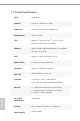
1.2 Product Specifications English 2 Color • Storm Black Material • Steel Body / Aluminum + Plastic Dimension • 372mm (W) x 123mm (H) x 400mm (L) Motherboard • ASRock Z87-M8 CPU • Supports 4th Gen Intel® CoreTM i7 / i5 / i3 / Xeon® / Pentium® / Celeron® Processor Family Memory • Supports DDR3 1600/1333/1066 MHz, 2 x SO-DIMM slots, Max. up to 16GB VGA • Supports 1 x Dual-slot Graphics Card* Optical Drive • 1 x Slim Slot-in Super-Multi Drive Hard Disk • Supports 3.5"HDD and 2.
M8 English * Max. Supported VGA Dimension: 290mm x 137mm x 43.5mm; Max. Supported TDP: 200W (If you use a graphics card with over 200W TDP, please note that the system’s power supply is only 450W.
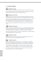
1.3 Unique Features ASRock A-Tuning A-Tuning is ASRock’s multi purpose software suite with a new interface, more new features and improved utilities, including XFast RAM, Dehumidifier, Good Night LED, FAN-Tastic Tuning, OC Tweaker and a whole lot more. ASRock Instant Flash ASRock Instant Flash is a BIOS flash utility embedded in Flash ROM. This convenient BIOS update tool allows you to update the system BIOS in a few clicks without preparing an additional floppy diskette or other complicated flash utility.
M8 ASRock XFast RAM ASRock XFast RAM is included in A-Tuning. It fully utilizes the memory space that cannot be used under Windows® 32-bit operating systems. ASRock XFast RAM shortens the loading time of previously visited websites, making web surfing faster than ever. And it also boosts the speed of Adobe Photoshop 5 times faster. Another advantage of ASRock XFast RAM is that it reduces the frequency of accessing your SSDs or HDDs in order to extend their lifespan.
ASRock Interactive UEFI ASRock Interactive UEFI is a blend of system configuration tools, cool sound effects and stunning visuals. The unprecedented UEFI provides a more attractive interface and more amusment. ASRock Fast Boot With ASRock’s exclusive Fast Boot technology, it takes less than 1.5 seconds to logon to Windows 8 from a cold boot. No more waiting! The speedy boot will completely change your user experience and behavior. ASRock Restart to UEFI Windows® 8 brings the ultimate boot up experience.
M8 ASRock Easy Driver Installer English For users that don’t have an optical disk drive to install the drivers from our support CD, Easy Driver Installer is a handy tool in the UEFI that installs the LAN driver to your system via an USB storage device, then downloads and installs the other required drivers automatically.
Chapter 2 Product Overview This chapter provides diagrams showing the location of important components of the M8. 2.1 Front View 1 2 3 4 No. English 1 2 3 4 5 6 8 5 6 Description A-Command (All-In-One OLED Button) Optical disk drive eject button 4 x USB 3.0 ports 4-in-1 Card reader (SD3.
M8 2.1.1 The Function of A-Command The A-Command is a multipurpose controller knob which is used to cycle through various functions. Controlling A-Command • Rotate the knob to toggle among main functions or options. • Press once to confirm your selection. Powering on the System Press A-Command to turn on the system power. Wait until the operating system loads automatically.
Under Windows: There are six main functions after entering the OS. English 10 • M8 Logo / Date and Time: After the logo appears for ten seconds, the screen shows date and time. The display will go off if you leave it idle for five minutes. • Volume: Increase/decrease the volume level by turning the knob right/left. • Mode: Toogle among three power management modes – Eco, Standard or Speed. • Info: Toggle among various types of critical information to check the system’s status.
M8 2.2 Rear View 1 1 2 3 3 Description PCIe slot covers I/O panel AC input power connector English No.
2.2.
M8 No. Description No. Description 1 Line In port (light blue) 10 eSATA2 port** 2 Line Out port (lime) 11 DisplayPort 3 Center/Subwoofer port (orange) 12 HDMI port 4 Rear Speaker Out port (black) 13 USB3.0 port 5 LAN RJ-45 port* (Intel Gigabit LAN) 14 USB3.0 port 6 USB2.0 ports 15 USB3.0 port 7 USB2.0 ports 16 USB3.0 port 8 USB2.0 ports 17 Optical SPDIF Out port 9 USB2.0 ports 18 Microphone port (pink) * There are two LEDs on the LAN port.
2.3 Inside View 3 2 1 4 6 7 9 8 10 12 11 13 5 14 15 17 16 No. 1 2 3 4 English 14 Description 5 Riser card retention bracket VGA card holder Hard disk drive tray (compatible with 4 x 2.5" HDD or 1 x 3.5 HDD) ODD + 2.5" HDD Tray (compatible with 1 x slot-in ODD and 1 x 2.5" HDD) Power supply unit (450W) 6 7 8 9 Power panel connector SATA 3.0 connectors USB2.
M8 10 11 12 13 14 Front audio connector USB3.0 connector Auxiliary fan connector 2T2R WiFi Module (802.11ac) CPU socket 15 DIMM sockets 16 Chassis fan connector 17 ATX 12V power connector English Hard drives are not included with this system.
Chapter 3 Hardware Installation This chapter helps you assemble the chassis and install components. Please follow the installation procedures listed below.
M8 3.1 Installing System Components 3.1.1 Removing the Side Panels To remove the side panels, you have to unlock the keylock on the top cover using the system key. Before unlocking, power off the system and unplug the power cord. After the side panel are replaced, make sure to lock the keylock on the top cover and then power on the system. 1. Place the system in an upright position. 2. Unlock the system keylock on the top cover. 3. Remove the side panels.
3.1.2 Removing the Top Cover 1. To remove the top cover, you have to follow the procedures below: 1) Power off the system and unplug the power cord. 2) Unlock the keylock on the top cover using the system key. 3) Follow the instructions in Section 3.1 to remove the right side panel. 4) Slide the top cover toward the front of the system until it releases from the latch. 2. After the top cover is replaced, make sure to lock the keylock on the top cover and then power on the system. 3.
M8 5. Draw out the mounting bracket from the chassis. 6. Follow the instructions in Section 3.1 to release the left side panel. 7. Release the top cover. 2 1 1 2 Slide the top cover toward the front of the system until it releases. Lift up the top cover. English 8. Disconnect the 4-pin top fan connector. 9. Set the top cover aside in a secure location.
3.1.3 Removing the VGA Card Holder To remove the VGA card holder, you have to remove the side panels and top cover, giving you access to the VGA card holder inside. 1. Remove the VGA card holder. 2 1 1 1 2 English 20 Remove the two screws that hold the VGA card holder in place. Lift the VGA card holder up and off the chassis.
M8 3.1.4 Removing the Riser Card 1. Remove the riser card. 1 1 Remove the two screws securing the riser card retention bracket. 2 Grasp the riser card by its edges, and carefully pull it from the expansion slot.
3.1.5 Installing the Hard Drives 3.1.5.1 Installing the Hard Drive(s) to the Drive Tray Assembly 1. To install the hard drives, you have to remove the VGA card holder and the riser card , giving you access to the drive tray assembly inside. 2. The drive tray assembly supports up to four 2.5-inch hard drives. You can also choose to install one 3.5-inch hard drive. 3. Hard drives are not included with this system. 1. Remove the drive tray assembly.
M8 2. Take apart the drive tray assembly. 1 2 1 1 1 Remove the screws that secure the bottom HDD tray with the top tray. 2 Take the assembly apart. 1 3. Install a 3.5" HDD or up to four 2.5" HDD. Installing a 3.5-Inch Hard Drive: 2 1 2 2 Set the top tray aside. Place a 3.5" HDD to the bottom HDD tray with the printed circuit board side facing down. Carefully align the mounting holes in the hard drive and the tray. 2 Secure the hard drive using the three screws (three on the sides).
Installing up to Four 2.5-Inch Hard Drive 4 3 5 2 1 5 5 1 2 3 4 5 Place the first 2.5" HDD to the bottom HDD tray and secure the hard drive using the four screws (two on the sides and two in the rear). Place the second 2.5" HDD to the top HDD tray and secure the hard drive using the four screws. Secure the third HDD to the top HDD tray. Secure the fourth HDD to the top HDD tray. Attach the top HDD tray to the bottom HDD tray using four screws. 4. Place the drive tray back into the chassis.
M8 3.1.5.2 Installing the Hard Drive to the ODD + 2.5" HDD Tray 1. To install the hard drives, you have to remove the PSU. 2. The ODD + 2.5” HDD Tray fits a slim slot-in optical disk drive (ODD) and a 2.5-inch hard drives. 3. Hard drives are not included with this system. Installing a 2.5-Inch Hard Drive 1. Remove the PSU. 1 3 2 Unplug the PSU power cable. Remove the two screws securing the power supply unit. 3 Slide the PSU to the right until it releases. Lift the PSU and set it aside.
2. Remove the ODD+2.5" HDD Tray. 2 2 2 3 1 1 Unplug the ODD SATA power connector. Remove the five screws securing the ODD + 2.5" HDD Tray to the chassis. 3 Lift the tray off the chassis. 2 3. Place a 2.5" HDD to the HDD tray and secure the hard drive using the four screws (four in the rear).
M8 4. Align the screw holes on the ODD + 2.5" HDD Tray with the screw holes on the chassis. Fasten the five screws. 5. Connect the power and SATA data cables and the ODD SATA power connector. 6. Re-install the PSU. 2 1 3 Align the PSU with the starting line and then slide the PSU to the left until it reaches the end line. Make sure that it clicks into place. 2 Re-plug the PSU power cable. 3 Secure the two screws securing the power supply unit.
3.1.6 Replacing the ODD 1. Follow the instructions in section 3.1.5.2 to remove the power supply unit and lift the tray off the chassis. 2. Remove the old optical disk drive. 3. Slide a new optical disk drive into the ODD tray. 4. Attach the optical disk drive to the ODD tray using screws. 5. Connect the ODD SATA power connector. 6. Follow the instructions in section 3.1.5.2 to replace the ODD + 2.5" HDD Tray and the power supply unit.
M8 3.1.7 Installing the CPU 1. Before you insert the 1150-Pin CPU into the socket, please check if the PnP cap is on the socket, if the CPU surface is unclean, or if there are any bent pins in the socket. Do not force to insert the CPU into the socket if above situation is found. Otherwise, the CPU will be seriously damaged. 2. Unplug all power cables before installing the CPU.
3 4 English 30
M8 English Please save and replace the cover if the processor is removed. The cover must be placed if you wish to return the motherboard for after service.
3.1.
M8 English 1. Make sure to evenly spread the thermal paste over the CPU to improve heat dissipation. 2. Ensure that the CPU and the CPU cooler are securely fastened and in good contact with each other. 3. To make sure the CPU cooler is seated properly, it is highly recommended to check whether or not the CPU temperature reported in the BIOS is at a normal level.
3.1.9 Installing Memory Modules (SO-DIMM) This motherboard provides two 204-pin DDR3 (Double Data Rate 3) SO-DIMM slots. It is not allowed to install a DDR or DDR2 memory module into a DDR3 slot; otherwise, this motherboard and SO-DIMM may be damaged. The DIMM only fits in one correct orientation. It will cause permanent damage to the motherboard and the DIMM if you force the DIMM into the slot at incorrect orientation.
M8 1 2 English 3 35
3.2 Replacing System Components 3.2.1 Replacing the Riser Card 1. Replace the riser card. 2 1 Align the riser card keys correctly with the expansion slot on the system board and insert it into place. 2 Fasten the two screws securing the riser card retention bracket.
M8 3.2.2 Installing the Graphics Card The M8 chassis supports both single-slot graphics card and dual-slot graphics card. Before graphics card installation, please lift the VGA card holder and make sure the riser card is installed properly. 1. Open the latch of the VGA card holder and remove the screws that secures the slot cover. 2. Remove the slot cover(s) on the VGA card holder. 3. Place your graphics card to the VGA card holder and secure it using screw(s). 4.
5. Engage the VGA card holder with the two vertical sliding tracks while sliding it back to the chassis. 6. Make sure the VGA card holder is secured by the tongue plate and the graphics card is seated correctly. English 7. Secure the VGA card holder with the chassis using the two screws previously removed.
M8 3.2.3 Replacing the Top Cover 1. Place the system in an upright position. 2. Make sure to release the left side panel. 3. Connect the 4-pin top fan connector. 4. Replace the top cover. 1 2 Replace the top cover onto the chassis. 2 Slide the top cover toward the rear of the system until it clicks into place.
5. Insert the mounting bracket into the mounting holes. 6. Secure it to the case with the three screws previously removed.
M8 3.2.1 Replacing the Side Panels 1. Place the system in an upright position. 2. Replace the side panels. 2 1 2 1 Snap the right side panel into place. Snap the left side panel into place. English 3. Lock the system keylock on the top cover.
Chapter 4 Motherboard 4.1 Motherboard Layout 1 4 3 2 6 5 7 8 9 PCIE1 SATA3_1 1 USB_1_2 1 64Mb BIOS SATA3_4 Center: FRONT WiFi-802.11ac Module Sound CORE3D Bottom: MIC IN CLRCMOS1 1 USB3_3_4 SATA3_3 Intel Z87 Bottom: Optical SPDIF SATA3_6 Top: LINE IN LPC1 MINI_PCIE1 Center: REAR SPK AUX_FAN1 PANEL1 15 HD_AUDIO1 1 SATA3_5 Top: CTR BASS PLED PWRBTN HDLED RESET SATA3_2 14 USB 3.0 T: USB0 B: USB1 USB 2.0 T: USB6 B: USB7 HDMI eSATA1 FSB800 USB 3.
M8 No. Description 1 System Panel Header (PANEL1) 2 LPC Debug Header (LPC1) 3 SATA3 Connectors 4 Clear CMOS Jumper (CLRCMOS1) 5 Auxiliary Fan Connector (AUX_FAN1) 6 USB 2.0 Header (USB_1_2) 7 mini-PCI Express Slot (MINI_PCIe1) 8 WiFi-802.
4.2 Jumpers Setup The illustration shows how jumpers are setup. When the jumper cap is placed on the pins, the jumper is “Short”. If no jumper cap is placed on the pins, the jumper is “Open”. The illustration shows a 3-pin jumper whose pin1 and pin2 are “Short” when a jumper cap is placed on these 2 pins. Clear CMOS Jumper (CLRCMOS1) (see p.41, No. 31) Default Clear CMOS CLRCMOS1 allows you to clear the data in CMOS.
M8 4.3 Onboard Headers and Connectors Onboard headers and connectors are NOT jumpers. Do NOT place jumper caps over these headers and connectors. Placing jumper caps over the headers and connectors will cause permanent damage to the motherboard. System Panel Header (9-pin PANEL1) (see p.41, No. 1) 1 HDLED+ PLED+ HDLED- PLED- GND RESET# GND PWRBTN# GND Connect the power switch, reset switch and system status indicator on the chassis to this header according to the pin assignments below.
Serial ATA3 Connectors (SATA3_1) (SATA3_2) (SATA3_5) (SATA3_6) (SATA3_3) (SATA3_4) (see p.41, No. 3) These six SATA3 connectors support SATA data cables for internal storage devices with up to 6.0 Gb/s data transfer rate. SATA3_4 connector is shared with the eSATA port. SATA3_1 SATA3_2 SATA3_5 SATA3_6 SATA3_3 SATA3_4 USB 2.0 Headers (9-pin USB_1_2) (see p.41, No.
M8 Front Panel Audio Header (9-pin HD_AUDIO1) (see p.41, No. 9) MIC2_L MIC2_R OUT2_R J_SENSE OUT2_L 1 This header is for connecting audio devices to the front audio panel. OUT_RET MIC_RET PRESENCE# GN D 1. High Definition Audio supports Jack Sensing, but the panel wire on the chassis must support HDA to function correctly. Please follow the instructions in our manual and chassis manual to install your system. 2.
ATX Power Connector (24-pin ATXPWR1) (see p.41, No. 5) ATX 12V Power Connector (4-pin ATX12V1) (see p.41, No. 13) LPC Debug Header (13-pin LPC1) (see p.41, No. 2) English 48 13 1 24 12 This motherboard provides a 24-pin ATX power connector. To use a 20-pin ATX power supply, please plug it along Pin 1 and Pin 13. This motherboard provides a 4-pin ATX 12V power connector. To use a 8-pin ATX power supply, please plug in 4 of the 8 pins (Pin 1 to Pin 4).
M8 Chapter 5 Software and Utilities Operation 5.1 Installing Drivers The Support CD that comes with the M8 contains necessary drivers and useful utilities that enhance the M8’s features. Running The Support CD To begin using the support CD, insert the CD into your CD-ROM drive. The CD automatically displays the Main Menu if “AUTORUN” is enabled in your computer. If the Main Menu does not appear automatically, locate and double click on the file “ASRSETUP.EXE” in the Support CD to display the menu.
5.2 A-Tuning A-Tuning is ASRock’s multi purpose software suite with a new interface, more new features and improved utilities, including XFast RAM, Dehumidifier, Good Night LED, FAN-Tastic Tuning, OC Tweaker and a whole lot more. 5.2.1 Installing A-Tuning When you install the all-in-one driver to your system from ASRock’s support CD, A-Tuning will be auto-installed as well. After the installation, you will find the icon “A-Tuning“ on your desktop.
M8 Tools Various tools and utilities. XFast RAM Boost the system’s performance and extend the HDD’s or SDD’s lifespan! Create a hidden partition, then assign which files should be stored in the RAM drive. XFast LAN Boost the speed of your internet connection! Select a specific mode for making the designated program's priority highest. Fast Boot Fast Boot minimizes your computer's boot time.
Dehumidifier Prevent motherboard damages due to dampness. Enable this function and configure the period of time until the computer powers on, and the duration of the dehumidifying process. Key Master Enhance your mouse and keyboard with customizable macros, sniper modes, scroll speed, key repeat rates and repeat delay. USB Key Plug in the USB Key and let your computer log in to windows automatically! OC DNA In OC DNA, you can save your OC settings as a profile and share with your friends.
M8 OC Tweaker Configurations for overclocking the system. System Info English View information about the system.
Live Update Check for newer versions of BIOS, A-Tuning or drivers. Tech Service Contact Tech Service.
M8 Settings English Configure ASRock A-Tuning.
5.3 SBX Pro Studio This section explains how to configure the Creative Sound Core3D using SBX Pro Studio. Click the power button on the left to activate or deactivate. Surround Control the level of audio immersion in music, movies and games. Crystalizer Enhance music and movies to make them sound livelier. Bass Control the desired level of bass. Crossover Frequency Redirect all frequencies below this value to the optimal speaker for better bass response.
M8 CRYSTALVOICE Select a recording device Mic Volume Control the level of mic volume. Mic Boost Control the level of mic boost. CrystalVoice Click the power button on the left to activate or deactivate. FX Morph your voice into different characters and accents. Smart Volume Be heard clearly without having to shout or whisper. Noise Reduction English Eliminate unwanted background noise in your conversation. Acoustic Echo Cancellation Eliminate echoes that interfere with your conversation.
SCOUT MODE Scout Mode Enable or disable scout mode. This proprietary technology allows you to hear your enemies from further away, giving you a distinct tactical advantage in combat. Hot Key Configuration Configure hot keys to enable or disable scout mode.
M8 SPEAKERS/HEADPHONES Speakers / Headphones Configuration Select the device connected. If there are both speakers and front headphones connected, please select the device you desire to use as audio output. Optional Speakers Center Enable or disable center speaker. Subwoofer Enable or disable subwoofer. Rear pair English Enable or disable rear pair speakers. Full-Range Speakers: Select full-range speakers.
Bass Management Bass Redirection Enable or disable bass redirection. Subwoofer Gain Enable or disable subwoofer gain. Crossover Frequency Redirect all frequencies below this value to the optimal speaker for better bass response. MIXER Playback Speakers Control the level of speakers playback. SPDIF-Out English Control the level of SPDIF-Out playback. Balance Control the level of various speaker’s balance.
M8 REC What U Hear Control the level of playback redirect. EQUALIZER EQ Choose from Flat, Acoustic, Classical, Country, Dance, Jazz, New Age, Pop, Rock and Vocal. JACK SETUP Device Connected: Select the device connected. Show Jack Setup dialog when an audio jack is inserted English Enable or disable Jack Setup dialog.
ADVANCED FEATURES Play stereo mix to digital output Enable or disable play stereo mix to digital output.
M8 User Profiles You can save, load or delete your user profiles. The default is . 1. If you want to hear your own voice through the microphone (Playback mode). You can change your settings to "playback mode" by checking the "Listen to this device" box in Control panel > Sound > Recording > Microphone > Properties > Listen. 2.
5.4 Intel® Rapid Start Technology Intel® Rapid Start Technology enables your system to wake up faster from deep sleep, saving time and power consumption. Feel secure to know that your system will resume to working condition even if an unexpected power loss happens while the PC is in sleep mode. 5.4.1 System Requirements • Confirm whether your motherboard supports this feature. • Operating system: Microsoft Windows 8/7 (32- or 64-bit edition) • Set the SATA mode to AHCI.
M8 3. Exit the Registry Editor window and restart the computer. 4. Press F2 to enter BIOS, then go to Advanced ‐> Storage Configuration and change SATA Mode to AHCI. Press F10 to save changes and exit. 5. Enter Windows 8/7. Windows will discover the new device and install AHCI drivers automatically. 5.4.2 Setup Guide Configuring Rapid Start Step 1 Run ASRock Rapid Start utility from Start -> All Programs -> ASRock Utility.
Step 3 When prompted to restart after the setup, click Yes to reboot. Step 4 Double-click the Intel® Rapid Start Technology Manager icon system tray.
M8 Step 5 Make sure Rapid Start is on. Drag the slider to configure the time. For example, if the timer value is set to ten minutes, the system will enable Rapid Start mode after entering sleep state for ten minutes. If the timer is set to 0 minutes, Windows will immediately enable Rapid Start mode as it enters sleep state. 1. You may shut down the computer without terminating the applications or files you are executing currently. Click on Windows Start ‐> the arrow next to Shut down, and click on Sleep.
will automatically wake up and enable Rapid Start mode after entering sleep state for a period of time. The power of the computer in Rapid Start mode can be cut off, it will not cause data loss of the programs or files you were executing before entering sleep state. 4. English 68 When you wish to continue to use the computer just hit the power button, the system will rapidly return to Windows, the programs and files which you were using before entering sleep state will be accessible immediately.
M8 5.5 Intel® Smart Connect Technology Intel® Smart Connect Technology is a feature that periodically wakes your computer from Windows® sleep state to refresh email or social networking applications. It saves your waiting time and keeps the content always up-to-date. 5.5.1 System Requirements • Confirm whether your motherboard supports this feature. • Operating system: Microsoft Windows 8/7 (32- or 64-bit edition) • Set the SATA mode to AHCI.
5.5.2 Setup Guide Installing ASRock Smart Connect Utility Step 1 Install ASRock Smart Connect Utility, which is located in the folder at the following path of the Support CD: \ ASRock Utility > Smart Connect. Step 2 Once installed, run ASRock Smart Connect from your desktop or go to Windows Start -> All Programs -> ASRock Utility.
M8 Step 3 Click the Add button. Take Foxmail as an example, add Foxmail to the Application list. Step 4 Select Foxmail from the Application List, then click the arrow pointing right to add this application to the Smart Connect List. English Step 5 Click Apply to enable Smart Connect.
Step 6 Double-click the Intel® Smart Connect Technology Manager icon Windows system tray. in the Step 7 Drag the slider to configure how often the system will connect to the network to download updates. Shorter durations will provide more frequent updates, but may cause more power consumption. Using Smart Connect English 72 1. Keep the applications which you wish to connect to the internet and receive updates while the system is in sleep state running. Foxmail for instance, keep Foxmail running. 2.
4. The system will wake up from sleep state periodically, and then start to update Foxmail. The screen will not display anything so the computer can maintain minimum power usage. Afterwards, the system will automatically return to sleep state again. 5. Upon waking up the system, you will find the new mail that were sent to you during sleep state are already updated and ready to be read in Foxmail.
5.6 Intel® Remote Wake Technology Intel® Remote Wake Technology allows you to use programs or services over the Internet to wake up your home computer from energy efficient sleep mode. Before configuring this feature, verify the following. • Remote Wake has been enabled in "Intel® Smart Connect Technology Manager". • Make sure that the "PCI Device Power On" is enabled in UEFI SETUP UTILITY > Advanced > ACPI Configuration. *Intel Remote Wake is supported on Win8 or Win8 64bit OS. 5.6.
M8 Step 2 Click the "My Account" tab. Then click on "New" to create a new mesh. Step 3 A new mesh window will pop up. Enter a mesh name and password. Step 4 Select all the checkboxes and click Create Mesh. Downloading and Installing Mesh Agent Step 1 English Click Install on the My Account page. Step 2 Select the mesh and download both files. Make sure both files are in the same directory. Step 3 Right-click on MeshAgent.exe and select Run as administrator.
Step 4 Click Install / Update. Step 5 Wait a minute for the New Machine to appear in "My Device".
M8 Step 6 Check whether "Intel Remote Wake" appeared or not. Waking up Your PC using PC Step 1 On the "My Devices" page, click on Power Actions. Step 2 English Click on Wake or Sleep.
Waking up Your PC Using Mobile Device Before waking up your home computer using a mobile device, please log out of MeshCentral on other previously used computers or devices. Step 1 Login to meshcentral.com/m. Step 2 Select a Machine. Step 3 Click on Wake or Sleep.
M8 5.6.2 Configuring and Using Splashtop Splashtop is a remote desktop access software that lets you remotely access your home computer from your mobile device. Before configuring this feature, verify that "Remote Wake" has been enabled in "Intel® Smart Connect Technology Manager". Setup Guide Step 1 Download and install the Streamer on your home computer, which is located in the folder at the following path of the Support CD: \ ASRock Utility > Splashtop Streamer. Then enter your Splashtop Account.
Using Remote Control Step 1 In "Splashtop 2”, tap an online machine from the list to connect to your home computer. Step 2 Start remotely accessing your home computer. The functionality and price of the Splashtop APP and subscription fee is subject to change. Please check www.splashtop.com for for details.
M8 Accessing Data English Playing Video 81
5.7 Start8 For those Windows 8 users who miss the Start Menu, Start8 is an ideal solution that brings back the familiar Start Menu along with added customizations for greater efficiency. 5.7.1 Installing Start8 Install Start8, which is located in the folder at the following path of the Support CD: \ ASRock Utility > Start8. 5.7.2 Configuring Start8 Style Select between the Windows 7 style and Windows 8 style Start Menu. Then select the theme of the Start Menu and customize the style of the Start icon.
M8 Configure Configure provides configuration options, including icon sizes, which shortcuts you want Start Menu to display, quick access to recently used apps, the functionality of the power button, and more.
Control lets you configure what a click on the start button or a press on the Windows key does. Desktop Desktop allows you to disable the hot corners when you are working on the desktop. It also lets you choose whether or not the system boots directly into desktop mode and bypass the Metro user interface. About Displays information about Start8.
M8 5.8 XSplit Broadcaster XSplit Broadcaster is a desktop application designed to make your gameplay broadcasting, live-streaming and recording a lot easier and more fun to do, we are giving away the 3 months premium license which is worth US$24.95 for free! 5.8.1 Live Streaming Your Gameplay Step 1 Go to Start > All Programs > XSplit > XSplit Broadcaster to launch it. Step 2 English Log in with your own username and password. (If you do not have an XSplit account, click No XSplit account? to register.
Step 3 Go to Broadcast > Add Channels…. Step 4 Click Add.... Step 5 Select a platform for live streaming. *Before you start streaming, you need to register an account for the streaming service website, such as Twitch.tv, USTREAM, or other livestreaming services.
M8 Step 6 Fill in your platform's Username and Password. Based on your needs, configure the Video and Audio Encoding settings. Click OK. Step 7 English The channel then appears in your broadcast list. Click Apply and OK to save the settings.
Step 8 Go to Broadcast and select the platform to enable live streaming. A link to view your live Broadcast has been copied for you automatically. Simply press CTRL-V or right click and choose Paste to paste the link into the browser, and you can see your broadcast. To disable live streaming, go to Broadcast again and deselect the platform. 5.7.2 Recording Your Gameplay Step 1 Go to Broadcast > Local recording to start recording.
M8 Chapter 6 UEFI SETUP UTILITY 6.1 Introduction ASRock Interactive UEFI is a blend of system configuration tools, cool sound effects and stunning visuals. Not only will it make BIOS setup less difficult but also a lot more amusing. This section explains how to use the UEFI Setup Utility to configure your system. You may run the UEFI Setup Utility by pressing or right after you power on the computer, otherwise, the Power-On-Self-Test (POST) will continue with its test routines.
6.1.2 Navigation Keys Use < > key or < > key to choose among the selections on the menu bar, and use < > key or < > key to move the cursor up or down to select items, then press to get into the sub screen. You can also use the mouse to click your required item. Please check the following table for the descriptions of each navigation key.
M8 6.2 Main Screen When you enter the UEFI Setup Utility, the Main screen will appear and display the system overview. Active Page on Entry Select the default page when entering the UEFI setup utility. UEFI Guide English UEFI Guide is a quick tutorial for ASRock's UEFI setup Utility. You may abort the tutorial by pressing "esc".
6.3 OC Tweaker Screen In the OC Tweaker screen, you can set up overclocking features. Because the UEFI software is constantly being updated, the following UEFI setup screens and descriptions are for reference purpose only, and they may not exactly match what you see on your screen. Load Optimized GPU OC Setting You can use this option to load optimized GPU overclocking setting. Please note that overclocing may cause damage to your GPU and motherboard. It should be done at your own risk and expense.
M8 CPU Cache Ratio The CPU Internal Bus Speed Ratio. The maximum should be the same as the CPU Ratio. BCLK/PCIE Frequency The CPU speed is determined by the CPU Ratio multiplied with the BCLK. Increasing the BCLK will increase the internal CPU clock speed but also affect the clock speed of other components. Spread Spectrum Enable Spread Spectrum to reduce electromagnetic interference for passing EMI tests. Disable to achieve higher clock speeds when overclocking.
Short Duration Power Limit Configure Package Power Limit 2 in watts. When the limit is exceeded, the CPU ratio will be lowered immediately. A lower limit can protect the CPU and save power, while a higher limit may improve performance. Primary Plane Current Limit Configure the current limit of the CPU under Turbo Mode in ampere. A lower limit can protect the CPU and save power, while a higher limit may improve performance. GT Frequency Configure the frequency of the integrated GPU.
M8 DRAM Configuration DRAM Tweaker Fine tune the DRAM settings by leaving marks in checkboxes. Click OK to confirm and apply your new settings. CAS# Latency (tCL) The time between sending a column address to the memory and the beginning of the data in response. RAS# to CAS# Delay (tRCD) The number of clock cycles required between the opening of a row of memory and accessing columns within it.
RAS# Active Time (tRAS) The number of clock cycles required between a bank active command and issuing the precharge command. Command Rate (CR) The delay between when a memory chip is selected and when the first active command can be issued. Write Recovery Time (tWR) The amount of delay that must elapse after the completion of a valid write operation, before an active bank can be precharged.
M8 tREFI Configure refresh cycles at an average periodic interval. tCKE Configure the period of time the DDR3 initiates a minimum of one refresh command internally once it enters Self-Refresh mode. tRDRD Configure between module read to read delay. tRDRDDR Configure between module read to read delay from different ranks. tRDRDDD Use this to change DRAM tRWSR Auto/Manual settings. The default is [Auto]. tWRRD Configure between module write to read delay.
tRDWR Configure between module read to write delay. tRDWRDR Configure between module read to write delay from different ranks. tRDWRDD Configure between module read to write delay from different DIMMs. RTL (CHA) Configure round trip latency for channel A. RTL (CHB) Configure round trip latency for channel B. IO-L (CHA) Configure IO latency for channel A. IO-L (CHB) Configure IO latency for channel B. ODT WR (CHA) Configure the memory on die termination resistors' WR for channel A.
M8 Command Tri State Enable for DRAM power saving. MRC Fast Boot Enable Memory Fast Boot to skip DRAM memory training for booting faster. FIVR Configuration FIVR Switch Frequency Signature Select whether to boost or lower the FIVR Switch Frequency. FIVR Switch Frequency Offset Configure the percentage of frequency boost or deduction. CPU Voltage Mode Auto: For optimized settings. Adaptive: Add voltage to the CPU when the system is under heavy load. Override: The voltage is fixed.
CPU Cache Voltage Offset Configure the voltage for the CPU Cache. Setting the voltage higher may increase system stability when overclocking. System Agent Voltage Offset Configure the voltage for the System Agent. Setting the voltage higher may increase system stability when overclocking. CPU Analog IO Voltage Offset CPU I/O Analog Voltage. CPU Digital IO Voltage Offset CPU I/O Digital Voltage.
M8 DRAM Voltage Use this to configure DRAM Voltage. The default value is [Auto]. PCH 1.05V Voltage Chipset 1.05V Voltage. Use default settings for best performance. PCH 1.5V Voltage English I/O 1.5V Voltage. Use default settings for best performance.
6.4 Advanced Screen In this section, you may set the configurations for the following items: CPU Configuration, Chipset Configuration, Storage Configuration, Intel® Rapid Start Technology, Intel® Smart Connect Technology, ACPI Configuration and USB Configuration. Setting wrong values in this section may cause the system to malfunction.
M8 6.4.1 CPU Configuration Active Processor Cores Select the number of cores to enable in each processor package. CPU C States Support Enable CPU C States Support for power saving. It is recommended to keep C3, C6 and C7 all enabled for better power saving. Enhanced Halt State (C1E) Enable Enhanced Halt State (C1E) for lower power consumption. CPU C3 State Support Enable C3 sleep state for lower power consumption. English CPU C6 State Support Enable C6 deep sleep state for lower power consumption.
Package C State Support Enable CPU, PCIe, Memory, Graphics C State Support for power saving. CPU Thermal Throttling Enable CPU internal thermal control mechanisms to keep the CPU from overheating. No-Execute Memory Protection Processors with No-Execution Memory Protection Technology may prevent certain classes of malicious buffer overflow attacks.
M8 6.4.2 Chipset Configuration Primary Graphics Adapter Select a primary VGA. VT-d Intel® Virtualization Technology for Directed I/O helps your virtual machine monitor better utilize hardware by improving application compatibility and reliability, and providing additional levels of manageability, security, isolation, and I/O performance. PCIE1 Link Speed Select the link speed for PCIE1.
Render Standby Power down the render unit when the GPU is idle for lower power consumption. Onboard HD Audio Enable/disable onboard HD audio. Set to Auto to enable onboard HD audio and automatically disable it when a sound card is installed. Front Panel Enable/disable front panel HD audio. Onboard HDMI HD Audio Enable audio for the onboard digital outputs. Onboard LAN Enable or disable the onboard network interface controller.
M8 6.4.3 Storage Configuration SATA Controller(s) Enable/disable the SATA controllers. SATA Mode Selection IDE: For better compatibility. AHCI: Supports new features that improve performance. RAID: Combine multiple disk drives into a logical unit. AHCI (Advanced Host Controller Interface) supports NCQ and other new features that will improve SATA disk performance but IDE mode does not have these advantages.
Dynamic Storage Accelerator Keep this option enabled for higher HDD and SDD I/O performance, lower latency and increased system responsiveness. Hard Disk S.M.A.R.T. S.M.A.R.T stands for Self-Monitoring, Analysis, and Reporting Technology. It is a monitoring system for computer hard disk drives to detect and report on various indicators of reliability.
M8 6.4.4 Intel® Rapid Start Technology Intel® Rapid Start Technology English Intel® Rapid Start Technology is a new zero power hibernation mode which allows users to resume in just 5-6 seconds.
6.4.5 Intel® Smart Connect Technology Intel® Smart Connect Technology Intel® Smart Connect Technology automatically updates your email and social networks, such as Twitter, Facebook, etc. while the computer is in sleep mode.
M8 6.4.6 ACPI Configuration Suspend to RAM Select disable for ACPI suspend type S1. It is recommended to select auto for ACPI S3 power saving. Check Ready Bit Enable to enter the operating system after S3 only when the hard disk is ready, this is recommended for better system stability. ACPI HPET Table Enable the High Precision Event Timer for better performance and to pass WHQL tests. PCIE Devices Power On English Allow the system to be waked up by a PCI device and enable wake on LAN.
RTC Alarm Power On Allow the system to be waked up by the real time clock alarm. Set it to By OS to let it be handled by your operating system. USB Keyboard/Remote Power On Allow the system to be waked up by an USB keyboard or remote controller. USB Mouse Power On Allow the system to be waked up by an USB mouse.
M8 6.4.7 USB Configuration USB Controller Enable or disable all the USB ports. USB 3.0 Controller Enable or disable all the USB 3.0 ports. Legacy USB Support Enable or disable Legacy OS Support for USB 2.0 devices. If you encounter USB compatibility issues it is recommended to disable legacy USB support. Select UEFI Setup Only to support USB devices under the UEFI setup and Windows/Linux operating systems only. Legacy USB 3.0 Support English Enable or disable Legacy OS Support for USB 3.0 devices.
6.5 Tools System Browser ASRock System Browser shows the overview of your current PC and the devices connected. OMG (Online Management Guard) Administrators are able to establish an internet curfew or restrict internet access at specified times via OMG. You may schedule the starting and ending hours of internet access granted to other users. In order to prevent users from bypassing OMG, guest accounts without permission to modify the system time are required.
M8 Easy Driver Installer For users that don’t have an optical disk drive to install the drivers from our support CD, Easy Driver Installer is a handy tool in the UEFI that installs the LAN driver to your system via an USB storage device, then downloads and installs the other required drivers automatically. Instant Flash Save UEFI files in your USB storage device and run Instant Flash to update your UEFI.
UEFI Download Server Select a server to download the UEFI firmware. Dehumidifier Function If Dehumidifier Function is enabled, the computer will power on automatically to dehumidify the system after entering S4/S5 state. Dehumidifier Period Configure the period of time until the computer powers on and enables Dehumidifier after entering S4/S5 state. Dehumidifier Duration Configure the duration of the dehumidifying process before it returns to S4/S5 state.
M8 6.6 Hardware Health Event Monitoring Screen This section allows you to monitor the status of the hardware on your system, including the parameters of the CPU temperature, motherboard temperature, fan speed and voltage. CPU Fan 1 Setting Select a fan mode for CPU Fans 1, or choose Customize to set 5 CPU temperatures and assign a respective fan speed for each temperature.
6.7 Boot Screen This section displays the available devices on your system for you to configure the boot settings and the boot priority. Fast Boot Fast Boot minimizes your computer's boot time. In fast mode you may not boot from an USB storage device. Ultra Fast mode is only supported by Windows 8 and the VBIOS must support UEFI GOP if you are using an external graphics card.
M8 Boot Beep Select whether the Boot Beep should be turned on or off when the system boots up. Please note that a buzzer is needed. Full Screen Logo Enable to display the boot logo or disable to show normal POST messages. AddOn ROM Display Enable AddOn ROM Display to see the AddOn ROM messages or configure the AddOn ROM if you've enabled Full Screen Logo. Disable for faster boot speed.
CSM Enable to launch the Compatibility Support Module. Please do not disable unless you’re running a WHCK test. If you are using Windows 8 64-bit and all of your devices support UEFI, you may also disable CSM for faster boot speed. Launch PXE OpROM Policy Select UEFI only to run those that support UEFI option ROM only. Select Legacy only to run those that support legacy option ROM only. Do not launch? Launch Storage OpROM Policy Select UEFI only to run those that support UEFI option ROM only.
M8 6.8 Security Screen In this section you may set or change the supervisor/user password for the system. You may also clear the user password. Supervisor Password Set or change the password for the administrator account. Only the administrator has authority to change the settings in the UEFI Setup Utility. Leave it blank and press enter to remove the password. User Password Set or change the password for the user account. Users are unable to change the settings in the UEFI Setup Utility.
6.9 Exit Screen Save Changes and Exit When you select this option the following message, “Save configuration changes and exit setup?” will pop out. Select [OK] to save changes and exit the UEFI SETUP Utility. Discard Changes and Exit When you select this option the following message, “Discard changes and exit setup?” will pop out. Select [OK] to exit the UEFI SETUP Utility without saving any changes. Discard Changes When you select this option the following message, “Discard changes?” will pop out.
M8 1 簡介 感謝您購買 M8,本電競準系統經 ASRock 嚴格品管製作,是一套讓人信賴的可 靠產品。本產品採耐用設計所展現的優異效能,完全符合 ASRock 對品質及耐 用度的承諾。 由於硬體規格可能會更新,所以本文件內容如有變更,恕不另行通知。如本文件有 任何修改,可至 ASRock 網站逕行取得更新版本,不另外通知。若您需要與本產品相 關的技術支援,請上我們的網站瞭解有關您使用機型的特定資訊。 ASRock 網站: http://www.asrock.com。 1.
1.2 產品規格 繁體中文 124 色彩 • 暴風黑 材質 • 鋼材 / 鋁合金 + 塑膠 尺寸 • 372 公釐 ( 寬 ) x 123 公釐 ( 高 ) x 400 公釐 ( 長 ) 主機板 • ASRock Z87-M8 CPU • 支援第 4 代 Intel® CoreTM i7 / i5 / i3 / Xeon® / Pentium® / Celeron® 處理器系列 記憶體 • 支援 DDR3 1600/1333/1066 MHz,2 x SO-DIMM 插 槽,最大 16GB VGA • 支援 1 x 雙槽顯示卡 光碟機 • 1 x 薄型吸入式 Super-Multi 光碟機 硬碟 • 支援 3.5 吋硬碟與 2.5 吋硬碟 WiFi + BT • 2T2R WiFi 802.11ac + BT v4.0 前置 I/O • 4 x USB 3.0、1 x MIC、1 x 耳機 • 4 合 1 讀卡機 (SD3.0/MMC/MS/MS PRO) 後置 I/O • 1 x 7.
M8 2 產品概述 本章提供 M8 重要元件位置的圖示。 2.1 前視圖 1 2 3 編號 1 2 3 4 5 6 5 6 繁體中文 4 說明 A-Command ( 萬用 OLED 按鈕 ) 光碟機退出按鈕 4 x USB 3.0 連接埠 4 合 1 讀卡機 (SD3.
2.1.
M8 在 Windows 下: 進入作業系統之後,共有六項主要功能。 • M8 標誌 / 日期與時間: 標誌出現十秒後,畫面即顯示日期與時間。 若讓顯示器閒置 5 分鐘,顯示器將熄滅。 • 音量: 左右轉動旋鈕,即可增加 / 減少音量。 • 模式: 切換三種電源管理模式 – 節能、標準或高速。 • 資訊: 切換各種不同的關鍵資訊類型,以檢查系統狀態。OLED 畫面顯示 CPU 頻率、CPU 使用率、LAN 使用率或 APM* 資料。 *APM ( 每分鐘操作數 ) 測量您可在一分鐘內執行多少次的鍵盤 / 滑鼠按一 下動作。若要瞭解自己手指的移動速度,請按一下 A-Command 開始計算 APM。再按一下 A-Command,即可停止計算。 • 燈光: 開啟 / 關閉機殼內的燈光,或啟用 Good Night LED ( 晚安 LED) 功能 *。 開:開啟機殼內的燈光 關:關閉機殼內的燈光 全關:關閉機殼內的燈光;啟用 Good Night LED ( 晚安 LED) 功能 *ASRock Good Night LED ( 晚安 LED) 技術會將不必要的 LED 關閉,以 營造更好的睡
2.
M8 2.2.
編號 說明 編號 說明 1 線路輸入連接埠 ( 淡藍色 ) 10 eSATA2 連接埠 ** 2 線路輸出連接埠 ( 萊姆色 ) 11 DisplayPort 3 中央 / 重低音連接埠 ( 橘色 ) 12 HDMI 連接埠 4 後喇叭輸出連接埠 ( 黑色 ) 13 USB3.0 連接埠 5 LAN RJ-45 連接埠 * (Intel Gigabit LAN) 14 USB3.0 連接埠 6 USB2.0 連接埠 15 USB3.0 連接埠 7 USB2.0 連接埠 16 USB3.0 連接埠 8 USB2.0 連接埠 17 光纖 SPDIF 輸出連接埠 9 USB2.
M8 2.3 內視圖 3 2 1 4 6 7 9 8 10 12 11 13 5 14 15 17 16 說明 1 2 3 4 擴充卡固定架 VGA 卡架 硬碟托盤 ( 相容於 4 x 2.5 吋 HDD 或 1 x 3.5 吋 HDD) ODD + 2.5 吋 HDD 托盤 ( 相容於 1 x 吸入式 ODD 與 1 x 2.5 吋 HDD) 5 電源供應器單元 (450W) 6 7 8 9 電源面板排針 SATA 3.0 接頭 USB 2.
10 11 12 13 14 15 16 17 前置音訊接頭 USB 3.0 排針 輔助風扇接頭 2T2R WiFi 模組 (802.
M8 1 简介 感谢您购买 M8,这是按照 ASRock 一贯严格质量控制标准生产的性能可靠的游 戏准系统。它提供符合 ASRock 质量和耐久性承诺的精良设计和卓越性能。 由于硬件规格可能已更新,因此,本文档的内容可能会随时更改,恕不另行通知。如 果本文档有任何修改,则更新的版本将发布在 ASRock 网站上,我们不会另外进行通 知。如果您需要与此产品相关的技术支持,请访问我们的网站以具体了解所用型号的 信息。 ASRock 网站: http://www.asrock.com. 1.
1.2 产品规格 �简体中文 134 颜色 • 风暴黑 材料 • 钢机身 / 铝 + 塑料 尺寸 • 372mm ( 宽 ) x 123mm ( 高 ) x 400mm ( 长 ) 主板 • ASRock Z87-M8 CPU • 支持 4 代 Intel® CoreTM i7 / i5 / i3 / Xeon® / Pentium® / Celeron® 处理器系列 内存 • 支持 DDR3 1600/1333/1066 MHz、2 x SO-DIMM 插槽, 最高 16GB VGA • 支持 1 x 双槽图形卡 光驱 • 1 x 簿型吸入式超级多功能光驱 硬盘 • 支持 3.5"HDD 和 2.5"HDD WiFi + BT • 2T2R WiFi 802.11ac + BT v4.0 前面 I/O • 4 x USB 3.0, 1 x MIC, 1 x 耳机 • 4 合 1 读卡器 (SD3.0/MMC/MS/MS PRO) 后面 I/O • 1 x 7.
M8 2 产品概览 本章通过图示介绍 M8 重要组件的位置。 2.1 前视图 1 2 4 编号 1 2 3 4 5 6 5 �简体中文 3 6 说明 A-Command(多合一 OLED 按钮) 光驱弹出按钮 4 x USB 3.0 端口 4 合 1 读卡器 (SD3.
2.1.
M8 Windows 下 : • M8 Logo / Date and Time(M8 标志 / 日期和时间): 标志显示 10 秒后,屏幕显示日期和时间。 如果闲置 5 分钟,显示屏幕会消失。 • Volume(音量): 通过左右转动旋钮增加 / 减小音量。 • Mode(模式): 在三个电源管理模式 Eco(节能)、Standard(标准)或 Speed(速度)之 间切换。 • Info(信息): 在不同类型的重要信息之间切换以检查系统的状态。OLED 屏幕显示 CPU 频率、CPU 使用、LAN 使用或 APM* 数据。 *APM(每分钟操作数)测量您在一分钟内可以执行的键盘 / 鼠标点击操 作数。要了解您手指的移动速度,按一下 A-Command 开始 APM 计数。 再按一下 A-Command 可停止它。 • Light(指示灯): 打开 / 关闭机壳上指示灯,或启用晚安指示灯功能 *。 On(开):打开机壳上指示灯 Off(关闭):关闭机壳上指示灯 All off(全关):关闭机壳上指示灯;启用晚安 LED 功能 *ASRock 晚安指示灯技术通过使多余的指示灯熄灭,让您有
2.
M8 2.2.
编号 说明 编号 说明 1 线路输入端口(淡蓝色) 10 eSATA2 端口 ** 2 线路输出端口(浅绿色) 11 DisplayPort 3 中央 / 低音扬声器端口(橙色) 12 HDMI 端口 4 后面扬声器输出端口(黑色) 13 USB3.0 端口 5 LAN RJ-45 端口 * (Intel Gigabit LAN) 14 USB3.0 端口 6 USB2.0 端口 15 USB3.0 端口 7 USB2.0 端口 16 USB3.0 端口 8 USB2.0 端口 17 光学 SPDIF 输出端口 9 USB2.
M8 2.3 内视图 3 2 1 4 6 7 9 8 10 12 11 13 5 14 15 17 编号 �简体中文 16 说明 1 2 3 4 转接卡固定支架 VGA 卡固定器 硬盘托盘(兼容 4 x 2.5" HDD 或 1 x 3.5 HDD) ODD + 2.5" HDD 托盘 (兼容 1 x 吸入式 ODD 和 1 x 2.5" HDD) 5 电源装置 (450W) 6 7 8 9 10 系统面板接脚 SATA 3.0 接口 USB 2.
11 12 13 14 15 16 17 USB 3.0 接脚 辅助风扇接口 2T2R WiFi 模块 (802.
M8 1 Einleitung Vielen Dank, dass Sie sich für das M8 entschieden haben – ein zuverlässiges GamingBarebone-System, das konsequent unter der strengen Qualitätskontrolle von ASRock hergestellt wurde. Es liefert ausgezeichnete Leistung mit robustem Design, das ASRocks Streben nach Qualität und Beständigkeit erfüllt. Da die technischen Daten der Hardware aktualisiert werden können, kann der Inhalt dieser Dokumentation ohne Ankündigung geändert werden.
1.2 Produktspezifikationen Deutsch 144 Farbe • Storm Black Material • Stahlgehäuse / Aluminium + Kunststoff Abmessungen • 372 mm (B) x 123 mm (H) x 400 mm (L) Motherboard • ASRock Z87-M8 Prozessor • Unterstützt Intel® CoreTM-Prozessorfamilie i7 / i5 / i3 / Xeon® / Pentium® / Celeron® der 4. Generation Speicher • Unterstützt DDR3 1600/1333/1066 MHz, 2 x SO-DIMMSteckplätze, max.
M8 2 Produktübersicht Dieses Kapitel enthält Abbildungen mit den Positionen wichtiger Komponenten des M8. 2.1 Vorderseite 1 Deutsch 2 3 4 Nr. 1 2 3 4 5 6 5 6 Beschreibung A-Command (Alles-in-Einem-OLED-Taste) Auswurftaste des optischen LaufwerksA-Command 4 x USB 3.0-Ports 4-in-1-Kartenleser (SD 3.
2.1.1 Die Funktion von A-Command Der A-Command ist ein Mehrzweckkontrollregler zum Umschalten zwischen verschiedenen Funktionen. A-Command steuern • Drehen Sie den Knopf zum Umschalten zwischen Hauptfunktionen und Optionen. • Drücken Sie zum Bestätigen Ihrer Auswahl einmal. System einschalten Drücken Sie zum Einschalten des Systems A-Command. Warten Sie, bis das Betriebssystem automatisch lädt.
M8 Unter Windows: • M8-Logo / Datum und Uhrzeit: Nachdem das Logo zehn Sekunden angezeigt wird, erscheinen Datum und Uhrzeit im Bildschirm. Das Display erlischt nach fünfminütiger Inaktivität. • Lautstärke: Lautstärke durch Drehen des Knopfs nach rechts/links erhöhen/verringern. • Modus: Zwischen drei Energieverwaltungsmodi umschalten – Energiesparen, Standard und Geschwindigkeit. • Info: Zwischen verschiedenen Arten kritischer Informationen zur Prüfung des Systemstatus umschalten.
2.2 Rückseite 1 Nr.
M8 1 2 18 3 4 17 5 6 7 15 16 13 14 11 12 Deutsch 2.2.
Nr. Beschreibung Nr. Beschreibung 1 Line-In-Port (hellblau) 10 eSATA2-Port** 2 Line-Out-Port (grün) 11 DisplayPort 3 Center/Subwoofer-Port (orange) 12 HDMI-Port 4 Rückseitiger Lautsprecherausgang (schwarz) 13 USB 3.0-Port 5 LAN-RJ-45-Port* (Intel-Gigabit-LAN) 14 USB 3.0-Port 6 USB 2.0-Ports 15 USB 3.0-Port 7 USB 2.0-Ports 16 USB 3.0-Port 8 USB 2.0-Ports 17 Optischer SPDIF-Ausgang 9 USB 2.0-Ports 18 Mikrofonanschluss (rosa) * Es gibt zwei LEDs am LAN-Port.
M8 2.3 Innenseite 3 2 1 4 6 7 9 8 10 12 11 13 5 Deutsch 14 15 17 16 Nr. 1 2 3 Beschreibung 5 Riser-Kartenhalterung VGA-Kartenhalterung Festplatteneinschub (kompatibel mit vier 2,5-Zoll-Festplatten oder 1 x 3,5-ZollFestplatte) ODD- + 2,5-Zoll-Festplatteneinschub (kompatibel mit einem optischem Slot-In-Laufwerk und einer 2,5-Zoll-Festplatte) Netzteil (450 W) 6 7 8 9 Systemblende-Stileiste SATA 3.0-Anschlüsse USB 2.
10 11 12 13 14 15 16 17 Vorderer Audioanschluss USB 3.0-Stileisten Zusatzlüfteranschluss 2T2R-WLAN-Modul (802.11ac) CPU-Sockel DIMM-Steckplätze Gehäuselüfteranschluss ATX-12-V-Netzanschluss Festplatten sind nicht im Lieferumfang dieses Systems enthalten.
M8 1 Introduction Nous vous remercions d’avoir acheté le M8, un mini-châssis fabriqué conformément au contrôle de qualité rigoureux et constant appliqué par ASRock. Fidèle à son engagement de qualité et de durabilité, ASRock vous garantit une carte mère de conception robuste aux performances élevées. Les spécifications matérielles pouvant être mises à jour, le contenu de ce document est soumis à modification sans préavis.
1.2 Spécifications du produit Français 154 Coloris • Noir orage Matériaux • Corps en acier / aluminium + plastique Dimensions • 372mm (L) x 123mm (H) x 400mm (l) Carte mère • ASRock Z87-M8 Processeur • Prend en charge les processeurs 4ème Génération Intel® CoreTM i7 / i5 / i3 / Xeon® / Pentium® / Celeron® Mémoire • Prend en charge DDR3 1600/1333/1066 MHz, 2 x fentes SO-DIMM, jusqu'à 16Go max.
M8 2 Vue d'ensemble du matériel Ce chapitre comprend des diagrammes illustrant l'emplacement de composants critiques de votre châssis M8. Français 2.1 Vue avant 1 2 3 4 No. 1 2 3 4 5 6 5 6 Description A-Command (bouton OLED tout-en-un) Bouton d'éjection du lecteur optique 4 x ports USB 3.0 Lecteur de cartes 4 en 1 (SD3.
2.1.1 Fonction de la A-command La A-command est un bouton multifonction qui permet de sélectionner diverses fonctionnalités. Contrôle de la A-command • Faites tourner le bouton pour sélectionner une fonction principale ou une option. • Appuyez une fois pour confirmer votre choix. Mise en route du système Français Appuyez sur la A-command pour allumer le système.
M8 Sous Windows : • Logo M8 / date et heure : Le logo s'affiche pendant dix secondes, puis la date et l'heure apparaissent sur l'écran. L'écran s'éteint automatiquement en l'absence d'activité pendant cinq minutes. • Volume : Augmentez/diminuez le volume en tournant le bouton principal vers la gauche/ droite. • Mode : Trois modes de gestion de l'alimentation sont disponibles - Eco, Standard et Speed. • Infos : Permet de consulter les informations critiques pour vérifier l'état du système.
2.2 Vue arrière 1 Français No.
M8 1 2 18 3 4 17 5 6 7 15 16 13 14 11 12 Français 2.2.
No. Description No. Description 1 Port entrée ligne (témoin bleu) 10 Port eSATA2** 2 Port sortie ligne (citron vert) 11 DisplayPort 3 Port Centre/Caisson de basse (orange) 12 Port HDMI 4 Port sortie haut-parleur arrière (noir) 13 Port USB3.0 5 Port LAN RJ-45* (Intel Gigabit LAN) 14 Port USB3.0 6 Ports USB2.0 15 Port USB3.0 7 Ports USB2.0 16 Port USB3.0 8 Ports USB2.0 17 Port sortie optique SPDIF 9 Ports USB2.
M8 2.3 Vue interne 3 2 1 4 7 9 8 10 12 11 Français 6 13 5 14 15 17 16 No. 1 2 3 Description 5 Support de maintien du rehausseur de carte Porte-carte VGA Plateau pour lecteur de disque dur (compatible avec 4 x HDD 2,5" ou 1 x HDD 3,5) Plateau ODD + HDD 2,5" (compatible avec 1 x ODD slot-in et 1 x HDD 2,5") Bloc d'alimentation (450W) 6 7 8 9 10 Embase du panneau système Connecteurs SATA 3.0 Embases USB 2.
11 12 13 14 15 16 17 Embases USB 3.0 Connecteurs du ventilateur auxiliaire Module WiFi 2T2R (802.11ac) Socket processeur Sockets DIMM Connecteurs du ventilateur du châssis Connecteur d’alimentation ATX 12V Les disques durs ne sont pas livrés avec ce système.
M8 1 Introduzione Congratulazioni per l’acquisto di M8, un sistema barebone di gioco affidabile prodotto secondo i severissimi controlli di qualità ASRock. La scheda madre offre eccellenti prestazioni con un design robusto che si adatta all'impegno di ASRock di offrire sempre qualità e durata. Italiano Poiché le specifiche hardware possono essere aggiornati, i contenuti di questa documentazione sono soggetti a modifiche senza preavviso.
1.
M8 2 Descrizione del prodotto Questo capitolo fornisce diagrammi che mostrano la posizione dei componenti chiave di M8. Italiano 2.1 Veduta frontale 1 2 3 4 No. 1 2 3 4 5 6 5 6 Descrizione A-Command (Tasto OLED All-In-One) Tasto d’espulsione unità ottica 4 x porte USB 3.0 Lettore di schede 4 in 1 (SD3.
2.1.1 Funzione della manopola A-Command A-Command è una manopola di regolazione polivalente utilizzata per scorrere tra varie funzioni. Controllo della manopola A-Command Italiano • Ruotare la manopola per passare tra le principali funzioni od opzioni. • Premere una volta per confermare la selezione. Accensione del sistema Premere la manopola A-Command per accendere il sistema. Attendere che il sistema operativo si carichi automaticamente.
M8 Windows: • Logo M8 / Data e ora: Dopo avere visualizzato il logo per dieci secondi, lo schermo mostra la data e l'ora. Il display si spegne se è lasciato inattivo per cinque minuti. • Volume: Permette di aumentare/diminuire il livello del volume girando la manopola verso destra/sinistra. • Mode (Modalità): Permette di passare fra tre modalità di risparmio energetico – Eco, Standard o Speed (Velocità).
2.2. Veduta posteriore Italiano 1 No.
M8 1 2 18 3 4 17 5 6 7 15 16 13 14 11 12 Italiano 2.2.
Italiano No. Descrizione No. Descrizione 1 Porta ingresso linea (azzurro) 10 Porta eSATA2* 2 Porta uscita linea (verde lime) 11 DisplayPort 3 Porta diffusore centrale/subwoofer (arancione) 12 4 Porta uscita diffusori posteriori (nero) 13 Porta USB3.0 5 Porta LAN RJ-45* (LAN Intel Gigabit) 14 Porta USB3.0 6 Porte USB2.0 15 Porta USB3.0 7 Porte USB2.0 16 Porta USB3.0 8 Porte USB2.0 17 Porta uscita ottica SPDIF 9 Porte USB2.
M8 2.3 Veduta interiore 3 1 Italiano 2 4 6 7 9 8 10 12 11 13 5 14 15 17 16 No. Descrizione 1 2 3 4 Staffa di contenimento della scheda riser Supporto scheda VGA Cassetto unità disco rigido (compatibile con 4 x HDD 2,5" o 1 x HDD 3,5") Cassetto ODD + HDD 2,5" (Compatibile con 1 x ODD slot-in e 1 x HDD 2,5") 5 Alimentatore (450W) 6 7 8 9 Header sul pannello del sistema Connettori SATA 3.0 Embases USB 2.
10 11 12 13 14 15 16 17 Connettore audio frontale Embases USB 3.0 Connettore ventola ausiliaria Modulo WiFi 2T2R (802.11ac) Socket CPU Prese DIMM Connettore ventola telaio Connettore alimentazione ATX 12V Italiano I dischi rigidi non sono inclusi con questo sistema.
M8 1 Introducción Español Gracias por adquirir su M8, un sistema fiable de pequeño formato para juegos fabricado siguiendo el estricto y constante control de calidad de ASRock. Proporciona un rendimiento excelente con un diseño resistente conforme al compromiso de calidad y durabilidad de ASRock. Dado que las especificaciones de hardware se pueden actualizar, el contenido de esta documentación está sujeto a cambio sin previo aviso.
1.
M8 2 Información general del producto En este capítulo se proporcionan diagramas que muestran la ubicación de los componentes importantes de su M8. Español 2.1 Vista frontal 1 2 3 4 5 6 Nº Descripción 1 2 A-Command (botón OLED todo en uno) Botón de expulsión de la unidad de disco ópticaA-Command (botón OLED todo en uno) 4 puertos USB 3.0 Lector de tarjetas 4 en 1 (SD3.
2.1.1 Función de A-Command A-Command es un mando de control multifunción que se utiliza para recorrer varias funciones. Español Controlar A-Command • Gire el mando para cambiar entre las funciones u opciones principales. • Presione una vez para confirmar la selección. Encender el sistema Presione A-Command para encender la alimentación del sistema. Espere a que el sistema operativo se cargue automáticamente.
M8 En Windows: • Logotipo de M8 y fecha y hora: Después de que aparezca el logotipo durante diez segundos, la pantalla muestra la fecha y hora. La pantalla se apagará si permanece inactiva durante cinco minutos. • Volumen: Suba o baje el nivel de volumen girando el mando hacia la derecha o hacia la izquierda. • Modo: Alterne entre tres modos de administración de energía: Eco, Estándar o Velocidad.
2.
M8 1 2 18 3 4 17 5 6 7 Español 2.2.
Nº Descripción Nº Descripción 1 Puerto de entrada de línea (azul claro) 10 Puerto eSATA2** 2 Puerto de salida de línea (verde lima) 11 DisplayPort 12 Puerto HDMI 13 Puerto USB3.0 Español 3 4 Puerto central y para amplificador de graves (naranja) Puerto Salida de los altavoces traseros (negro) 5 Puerto LAN RJ-45* (LAN Intel Gigabit) 14 Puerto USB3.0 6 Puertos USB2.0 15 Puerto USB3.0 7 Puertos USB2.0 16 Puerto USB3.0 8 Puertos USB2.
M8 Español 2.
Español 9 10 11 12 13 14 15 16 17 Ranura PCI Conector de audio frontal Cabezales USB 3.0 Conector para el ventilador auxiliar Módulo WiFi 2T2R (802.11ac) Zócalo para CPU Zócalos DIMM Conector para el ventilador del chasis Conector de alimentación ATX de 12 V Las unidades de disco duro no se incluyen con este sistema.
M8 Русский 1 Введение Благодарим вас за приобретение надежной игровой базовой системы M8, выпускаемой под постоянным строгим контролем компании ASRock. Система обеспечивает великолепную производительность и характеризуется прочной конструкцией в соответствии с требованиями компании ASRock в отношении качества и долговечности. В случае обновления спецификации на аппаратное обеспечение содержимое настоящей документации может быть изменено без предварительного уведомления.
Русский 1.
M8 Русский 2 Обзор изделия В данной главе представлены диаграммы расположения важных компонентов М8. 2.1 Вид спереди 1 2 3 4 5 6 № Описание 1 2 3 4 5 6 A-Command (Универсальная кнопка ОСИД) Кнопка извлечения оптического диска 4 порта USB 3.0 Устройство чтения карт 4-в-1 (SD3.
Русский 2.1.1 Функции A-Command A-Command - это многоцелевая ручка управления, которая используется для выбора различных функций. Управление с помощью кнопки "A-Command" • Поверните ручку для выбора основных функций или параметров. • Нажмите один раз для подтверждения выбора. Включение питания системы Чтобы включить питание системы, нажмите на кнопку "A-Command" Подождите, пока выполняется автоматическая загрузка операционной системы.
M8 Русский В ОС Windows: После входа в ОС доступно шесть основных функций. • Логотип M8 / Дата и время: Через десять секунд после появления логотипа на экране отображается дата и время. При отсутствии активности в течение пяти минут дисплей отключается. • Громкость: Чтобы увеличить/уменьшить громкость, поверните ручку вправо/влево. • Режим: Доступно три режима управления питанием: Эко, Стандартный и Скоростной.
Русский 2.
M8 1 2 18 3 4 17 5 6 7 Русский 2.2.
Русский № Описание № Описание 1 Порт линейного входа (голубой) 10 Порт eSATA2** 2 Порт линейного выхода (салатовый) 11 DisplayPort 3 Центральный канал/сабвуфер (оранжевый) 12 Порт HDMI 4 Порт выхода тыловых динамиков (черный) 13 Порт USB3.0 5 Порт LAN RJ-45* (Intel Gigabit LAN) 14 Порт USB3.0 6 Порты USB2.0 15 Порт USB3.0 7 Порты USB2.0 16 Порт USB3.0 8 Порты USB2.0 17 Оптический порт вывода SPDIF 9 Порты USB2.
M8 Русский 2.3 Вид внутри 3 2 1 4 6 7 9 8 10 12 11 13 5 14 15 17 16 № Описание 1 2 3 5 Скобка для крепления переходной платы Держатель карты VGA Лоток для жесткого диска (совместимый с 4 жесткими дисками 2,5'' или 1 жестким диском 3,5'') Лоток для оптического диска + жесткого диска 2,5'' (совместимый с 1 разъемом для подключения оптического диска и 1 жестким диском 2,5'') Блок питания (450 Вт) 6 7 8 Колодка системной панели Разъемы SATA 3.0 Колодки USB 2.0.
Русский 9 10 11 12 13 14 15 16 17 Гнездо PCIe Аудиоразъем на передней панели Колодки USB 3.0. Разъем дополнительного вентилятора Модуль 2T2R WiFi (802.11ac) Гнездо ЦП Гнезда DIMM Разъем вентилятора корпуса Разъем питания АТХ 12 В Данная система поставляется без жестких дисков.
M8 1 Introdução Obrigado por ter comprado o M8, um sistema barebone fiável para jogos produzido sob os rigorosos critérios de controlo de qualidade da ASRock. Este sistema oferece um excelente desempenho com um design robusto em conformidade com o compromisso da ASRock em fabricar produtos de qualidade e resistentes. Dado que as especificações do hardware poderão ser actualizadas, o conteúdo desta documentação estará sujeito a alterações sem aviso prévio.
1.2 Especificações do produto Português 194 Cor • Preto tempestade Material • Corpo em aço / Alumínio + Plástico Dimensões • 372 mm (L) x 123 mm (A) x 400 mm (C) Placa principal • ASRock Z87-M8 CPU • Suporta processadores Intel® CoreTM i7 / i5 / i3 / Xeon® / Pentium® / Celeron® de 4ª geração Memória • Suporta DDR3 1600/1333/1066 MHz, 2 x ranhuras SODIMM, Máx.
M8 2 Descrição geral do produto Este capítulo apresenta diagramas que mostram a localização dos componentes do sistema M8. 2.1 Vista frontal 1 2 3 4 1 2 3 4 5 6 6 Descrição A-Command (Botão OLED tudo em um) Botão de ejecção do disco óptico 4 x portas USB 3.0 Leitor de cartões 4-em-1 (SD3.0/MMC/MS/MS PRO) Tomada para microfone Tomada para auscultadores Português N.
2.1.1 A função do A-Command O A-Command é um botão controlador multifunções que é utilizado para percorrer as diversas funções. Controlar o A-Command • Rode o o botão para alternar entre as funções principais ou opções. • Prima uma vez para confirmar a sua selecção. Ligar o sistema Prima o botão A-Command para ligar o sistema. Aguarde que o sistema operativo carregue automaticamente.
M8 No Windows: Existem seis funções principais depois de entrar no SO. • Logótipo M8 / Data e hora: Após a exibição do logótipo durante dez segundos, o visor exibirá a data e hora. O visor irá desligar se estiver inactivo durante cinco segundos. • Volume: Aumentar/diminuir o nível do volume rodando o botão para a direita/esquerda. • Modo: Alternar entre três modos de gestão de energia - Eco, Normal ou Velocidade.
2.2 Vista posterior 1 N.
M8 2.2.
N.º Descrição N.º Descrição 1 Porta entrada de linha (azul claro) 10 Porta eSATA2** 2 Porta de saída de linha (verde claro) 11 DisplayPort 3 Porta de Subwoofer/Centro (laranja) 12 Porta HDMI 4 Porta de saída do altifalante traseiro (preto) 13 Porta USB3.0 5 Porta LAN RJ-45* (Intel Gigabit LAN) 14 Porta USB3.0 6 Portas USB 2.0 15 Porta USB3.0 7 Portas USB 2.0 16 Porta USB3.0 8 Portas USB 2.0 17 Porta de saída óptica SPDIF 9 Portas USB 2.
M8 2.3 Vista interna 3 2 1 4 6 7 9 8 10 12 11 13 5 14 15 17 16 1 2 3 4 Descrição Suporte de retenção da placa Suporte da placa VGA Compartimento da unidade de disco rígido (compatível com 4 x HDD de 2,5" ou 1 x HDD de 3,5") Compartimento de ODD + HDD de 2,5" HDD (compatível com 1 x ODD de entrada de ranhura e 1 x HDD de 2,5") 5 Fonte de alimentação (450W) 6 7 8 9 Terminal do painel de sistema Conectores SATA 3.0 Terminais USB 2,0 Ranhura PCIe Português N.
10 11 12 13 14 Conector de áudio do painel frontal Terminais USB 3,0 Conector da ventoinha auxiliar Módulo WiFi 2T2R (802.11ac) CPU socket Este sistema não inclui os discos rígidos.
M8 1 개요 ASRock 의 일관되고 엄격한 품질관리 하에 생산되어 신뢰성이 우수한 게이밍 베어본 시스템 M8 을 구입해 주셔서 감사합니다 . 이 시스템은 품질과 내구성에 대한 ASRock 의 기준에 부합하는 우수한 성능과 견고한 설계를 제공합니다 . 하드웨어을 업데이트할 수도 있기 때문에 , 이 문서의 내용은 예고 없이 변경될 수 있 습니다 . 이 설명서가 변경될 경우 , 업데이트된 버전은 ASRock 의 웹사이트에서 추가 통지 없이 제공됩니다 . 이 제품과 관련하여 기술적 지원이 필요한 경우 , 당사의 웹사 이트를 방문하여 사용 중인 모델에 대한 구체적 정보를 구하십시오 . ASRock 웹사이 트 : http://www.asrock.com. 1.
1.2 제품 규격 한국어 204 색 • 스톰 블랙 재질 • 강철 본체 / 알루미늄 + 플라스틱 치수 • 372mm (W) x 123mm (H) x 400mm (L) 마더보드 • ASRock Z87-M8 CPU • 4 세대 Intel® CoreTM i7 / i5 / i3 / Xeon® / Pentium® / Celeron® 프로세서 제품군 지원 메모리 • DDR3 1600/1333/1066 MHz, SO-DIMM 슬롯 2 개 , 최대 16GB 지원 VGA • 듀얼 슬롯 그래픽 카드 1 개 지원 광학 드라이브 • 슬림 슬롯 삽입식 Super-Multi 드라이브 1 개 지원 하드 디스크 • 3.5" HDD 및 2.5" HDD 지원 WiFi + BT • 2T2R WiFi 802.11ac + BT v4.0 지원 전면 I/O • USB 3.0 포트 4 개 , MIC 잭 1 개 , 헤드폰 잭 1 개 • 4-in-1 카드 리더 (SD3.
M8 2 제품 개요 이 장에서는 M8 의 중요 구성부품의 위치를 보여주는 다이어그램을 제공합니 다. 2.1 앞면 1 2 번호 1 2 3 4 5 6 설명 4 5 한국어 3 6 A-Command ( 올인원 OLED 버튼 ) 광학 디스크 드라이브 꺼내기 버튼 USB 3.0 포트 4 개 4-in-1 카드 리더 (SD3.
2.1.1 A-Command 의 기능 A-Command 는 여러 기능 사이에서 전환하는 데 사용되는 다목적 컨트롤러 스 위치입니다 . A-Command 조절 • 스위치를 돌려 주요 기능 또는 옵션 사이에서 전환합니다 . • 한 번 누르면 선택이 확인됩니다 . 시스템 켜기 A-Command 를 눌러 시스템 전원을 켭니다 . 운영체제가 자동으로 로드할 때까 지 기다립니다 . 시스템 끄기 OLED 가 M8 로고 / 날짜 및 시간을 표시하면 A-Command 를 눌러 "Yes"( 예 ) 를 선택하여 시스템 전원을 끕니다 . Windows 에 들어가기 전에 OS 에 들어가기 전에 사용되는 세 개의 주요 기능이 있습니다 . 한국어 206 • M8 로고 / 날짜 및 시간 : 로고가 10 초 동안 표시된 후 화면에서는 날짜와 시간을 표시합니다 . 5 분 동안 아무 작업도 하지 않을 경우 화면이 꺼집니다 . • 라이트 : 케이스의 라이트를 켜고 끕니다 . • 시간 : 시간을 켜고 끕니다 .
M8 Windows 에서 : OS 에 들어간 후 사용되는 여섯 개의 주요 기능이 있습니다 . • M8 로고 / 날짜 및 시간 : 로고가 10 초 동안 표시된 후 화면에서는 날짜와 시간을 표시합니다 . 5 분 동안 아무 작업도 하지 않을 경우 화면이 꺼집니다 . • 볼륨 : 스위치를 오른쪽 / 왼쪽으로 돌려 볼륨 레벨을 높이거나 낮춥니다 . • 모드 : 세 개의 전원 관리 모드 , 즉 Eco( 절전 모드 ), Standard( 표준 모드 ) 또는 Speed( 고속 모드 ) 사이에서 전환합니다 . • 정보 : 시스템의 상태를 점검하기 위한 중요 정보의 여러 유형 사이에서 전환합니 다 . OLED 화면에서는 CPU 주파수 , CPU 사용률 , LAN 사용률 또는 APM* 데이터를 표시합니다 . *APM ( 분당 동작수 (Actions per minute)) 은 일분에 수행할 수 있는 키보드 입력 / 마우스 클릭 횟수를 측정합니다 .
2.
M8 2.2.
번호 설명 번호 설명 1 라인 입력 포트 ( 담청색 ) 10 eSATA2 포트 ** 2 라인 출력 포트 ( 라임색 ) 11 DisplayPort 3 센터 / 서브우퍼 포트 ( 주황색 ) 12 HDMI 포트 4 후면 스피커 출력 포트 ( 검정 ) 13 USB3.0 포트 5 LAN RJ-45 포트 * (Intel Gigabit LAN) 14 USB3.0 포트 6 USB2.0 포트 15 USB3.0 포트 7 USB2.0 포트 16 USB3.0 포트 8 USB2.0 포트 17 광학 SPDIF 출력 포트 9 USB2.0 포트 18 마이크 포트 ( 분홍 ) * LAN 포트에는 LED 가 두 개가 있습니다 . LAN 포트 LED 지시 정보에 대해서는 아래 표를 참조하십시오 .
M8 2.3 내부 3 2 1 4 6 7 9 8 10 12 11 13 5 14 15 17 16 설명 1 2 3 4 라이저 카드 고정 브래킷 VGA 카드 홀더 하드 디스크 드라이브 트레이 (2.5" HDD 4 개 또는 3.5" HDD 1 개와 호환 ) ODD + 2.5" HDD 트레이 ( 슬롯 삽입식 ODD 1 개와 2.5" HDD 1 개와 호환 ) 5 전원공급장치 (450W) 6 7 8 9 10 시스템 패널 헤더 SATA 3.0 커넥터 USB 2.
11 12 13 14 15 16 17 USB 3.0 헤더 보조 팬 커넥터 2T2R WiFi 모듈 (802.11ac) CPU 소켓 DIMM 소켓 섀시 팬 커넥터 ATX 12V 전원 커넥터 하드 드라이브는 별도로 구입하셔야 합니다 .
M8 1 はじめに M8 をお買い上げいただきまして誠にありがとうございます。M8 は ASRock の一 貫した厳格な品質管理の下で製造された信頼性の高いゲーミングベアボーンシ ステムです。アスロックの品質と耐久性の取り組みに準拠した堅牢な設計を持つ、 優れたパフォーマンスを提供します。 ハードウェアの仕様は更新されることがあるため、 このマニュアルの内容は予告なしに変 更することがあります。このマニュアルの内容に変更があった場合には、更新されたバー ジョンは、予告なくアスロックのウェブサイトから入手できるようになります。この製品に 関係して技術サポートが必要な場合は、 ご使用のモデルに関する詳細情報について、弊 社ウェブサイトをご覧ください。ASRock ウェブサイト : http://www.asrock.com。 1.
1.2 製品仕様 日本語 214 色 • ストームブラック 材料 • スチール製本体 / アルミニウム + プラスチック 寸法 • 372mm ( 幅 ) x 123mm ( 高さ ) x 400mm ( 長さ ) マザーボード • ASRock Z87-M8 CPU • 第 4 世代 Intel® CoreTM i7 / i5 / i3 / Xeon® / Pentium® / Celeron® プロセッサー・ファミリーに対応 メモリ • DDR3 1600/1333/1066 MHz に対応、SO-DIMM スロット 2 個、最大 16GB VGA • デュアルスロットグラフィックスカード 1 枚に対応 光学ドライブ • スロットイン方式スリムスーパーマルチドライブ 1 台 ハードディスク • 3.5"HDD および 2.5"HDD に対応 WiFi + BT • 2T2R WiFi 802.11ac + BT v4.0 フロント I/O • 4 x USB 3.0、1 x マイク、1 x ヘッドフォン • 4-in-1 カードリーダー(SD3.
M8 2 製品の各部の名称 この章では、M8 の主要コンポーネントの位置を図で説明します。 2.1 前面図 1 2 日本語 3 4 番号 1 2 3 4 5 6 5 6 説明 A-Command(オールインワン OLED ボタン) 光学ディスクドライブのイジェクトボタン 4 x USB 3.0 ポート 4-in-1 カードリーダー(SD3.
2.1.
M8 Windows で使用できる機能 : OS を起動した後で、次の 6 つのメイン機能を使用できます。 • M8 Logo / Date and Time(M8 ロゴ / 日付と時刻): ロゴが 10 秒間表示された後で、画面に日付と時刻が表示されます。 5 分間アイドル状態のままにすると、 ディスプレイはオフになります。 • Volume(音量): ノブを右 / 左に回転して、音量レベルを高くします / 低くします。 • Mode(モード): 次の 3 つの電源管理モードを切り替えます – Eco(エコ) 、Standard(標準) 、 ま たは、Speed(高速)。 • Info(情報): さまざまな種類の重要な情報を切り替えて、 システムの状態を確認します。 OLED 画面に、CPU 周波数、CPU 使用率、LAN 使用率、 または、APM* デー タが表示されます。 *APM(Actions per minute、1 分あたりの操作量) で、1 分間にキーボードやマ ウスをクリックした回数を測定します。あなたの指の動きの速さを確認する には、A-command を 1 回押して A
2.
M8 2.2.
番号 説明 番号 説明 1 ライン入力ポート (明るい青色) 10 eSATA2 ポート ** 2 ライン出力ポート (ライム色) 11 DisplayPort 12 HDMI ポート 3 センター / サブウーファーポート (オレンジ色) 4 リアスピーカー出力ポート (黒色) 13 USB3.0 ポート 5 LAN RJ-45 ポート * (Intel Gigabit LAN) 14 USB3.0 ポート 6 USB2.0 ポート 15 USB3.0 ポート 7 USB2.0 ポート 16 USB3.0 ポート 8 USB2.0 ポート 17 オプティカル SPDIF 出力ポート 9 USB2.
M8 2.3 内側の図 3 2 1 4 6 7 9 8 10 12 11 13 5 14 15 17 日本語 16 番号 1 2 3 4 説明 ライザーカードのリテンションブラケット VGA カードホルダー ハードディスクドライブトレイ (4 x 2.5" HDD または 1 x 3.5 HDD に対応 します) ODD + 2.5" HDD トレイ (1 x スロットイン方式 ODD および 1 x 2.5" HDD に対応します) 5 電源供給ユニット (450W) 6 7 8 9 システムパネルヘッダー SATA 3.0 コネクター USB 2.
10 11 12 13 14 15 16 17 フロントオーディオコネクター USB 3.0 ヘッダー 補助ファンコネクター 2T2R WiFi モジュール (802.