G41M-VGS3 / G41M-VS3 User Manual Version 1.0 Published December 2009 Copyright©2009 ASRock INC. All rights reserved.
Copyright Notice: No part of this manual may be reproduced, transcribed, transmitted, or translated in any language, in any form or by any means, except duplication of documentation by the purchaser for backup purpose, without written consent of ASRock Inc. Products and corporate names appearing in this manual may or may not be registered trademarks or copyrights of their respective companies, and are used only for identification or explanation and to the owners’ benefit, without intent to infringe.
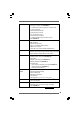
Contents 1 Introduction ................................................... 5 1.1 1.2 1.3 1.4 1.5 Package Contents .......................................................... Specifications ................................................................ Motherboard Layout (G41M-VGS3 / G41M-VS3) ......... I/O Panel (G41M-VGS3) ................................................ I/O Panel (G41M-VS3) ................................................... 5 6 10 11 12 2 Installation ...............................
Software Support ........................................... 50 4.1 Install Operating System ............................................... 4.2 Support CD Information ................................................. 4.2.1 Running Support CD ............................................ 4.2.2 Drivers Menu ........................................................ 4.2.3 Utilities Menu ........................................................ 4.2.4 Contact Information ..........................................
Chapter 1 Introduction Thank you for purchasing ASRock G41M-VGS3 / G41M-VS3 motherboard, a reliable motherboard produced under ASRock’s consistently stringent quality control. It delivers excellent performance with robust design conforming to ASRock’s commitment to quality and endurance. In this manual, chapter 1 and 2 contain introduction of the motherboard and step-by-step guide to the hardware installation. Chapter 3 and 4 contain the configuration guide to BIOS setup and information of the Support CD.
1.2 Specifications Platform CPU Chipset Memory Expansion Slot Graphics Audio LAN Rear Panel I/O 6 - Micro ATX Form Factor: 8.9-in x 6.7-in, 22.6 cm x 17.
Connector BIOS Feature Support CD Unique Feature Hardware Monitor OS Certifications - 4 x SATAII 3.0 Gb/s connectors (No Support for RAID and “Hot Plug” functions) (see CAUTION 7) - 1 x ATA100 IDE connector (supports 2 x IDE devices) - 1 x Print port header - CPU/Chassis FAN connector - 24 pin ATX power connector - 4 pin 12V power connector - Front panel audio connector - 2 x USB 2.0 headers (support 4 USB 2.0 ports) (see CAUTION 8) - 8Mb AMI BIOS - AMI Legal BIOS - Supports “Plug and Play” - ACPI 1.
WARNING Please realize that there is a certain risk involved with overclocking, including adjusting the setting in the BIOS, applying Untied Overclocking Technology, or using the thirdparty overclocking tools. Overclocking may affect your system stability, or even cause damage to the components and devices of your system. It should be done at your own risk and expense. We are not responsible for possible damage caused by overclocking. CAUTION! 1.
10. Featuring an advanced proprietary hardware and software design, Intelligent Energy Saver is a revolutionary technology that delivers unparalleled power savings. In other words, it is able to provide exceptional power saving and improve power efficiency without sacrificing computing performance. Please visit our website for the operation procedures of Intelligent Energy Saver. ASRock website: http://www.asrock.com 11. ASRock Instant Flash is a BIOS flash utility embedded in Flash ROM.
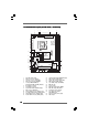
1.3 Motherboard LLayout ayout (G41MVGS3 / G41MVS3) (G41M-VGS3 G41M-VS3) 3 2 1 5 4 17.0cm (6.7 in) PS2 Mouse PS2_USB_PWR1 Intel G41 Chipset Super IO 25 Top: Line In Bottom: Mic In Center: Line Out LAN PHY HD_AUDIO1 FSB1 1 LPT1 1 6 EUP_LAN PCIE1 1 1 EUP_AUDIO1 AUDIO CODEC 19 18 17 FSB800 1 USB 2.0 T: USB0 Top: RJ-45 B: USB1 24 23 22 21 20 22.6cm (8.9 in) 26 FSB800 VGA1 EuP Ready FSB1333 DDR3 1333 Dual Channel COM1 USB 2.
1.4 I/O PPanel anel (G41MVGS3) (G41M-VGS3) 1 3 2 4 5 6 10 1 2 *3 4 5 9 7 8 PS/2 Mouse Port (Green) USB 2.0 Ports (USB23) RJ-45 Port Line In (Light Blue) Line Out (Lime) 6 7 8 9 10 Microphone (Pink) USB 2.
1.5 I/O PPanel anel (G41MVS3) (G41M-VS3) 1 3 2 4 5 6 10 1 2 *3 4 5 9 7 8 PS/2 Mouse Port (Green) USB 2.0 Ports (USB23) RJ-45 Port Line In (Light Blue) Line Out (Lime) 6 7 8 9 10 Microphone (Pink) USB 2.
Chapter 2 Installation G41M-VGS3 / G41M-VS3 is a Micro ATX form factor (8.9" x 6.7", 22.6 x 17.0 cm) motherboard. Before you install the motherboard, study the configuration of your chassis to ensure that the motherboard fits into it. Make sure to unplug the power cord before installing or removing the motherboard. Failure to do so may cause physical injuries to you and damages to motherboard components. 2.
2.3 CPU Installation For the installation of Intel 775-LAND CPU, please follow the steps below. 775-Pin Socket Overview Before you insert the 775-LAND CPU into the socket, please check if the CPU surface is unclean or if there is any bent pin on the socket. Do not force to insert the CPU into the socket if above situation is found. Otherwise, the CPU will be seriously damaged. CPU Marked Corner Step 1. Open the socket: Step 1-1.
For proper inserting, please ensure to match the two orientation key notches of the CPU with the two alignment keys of the socket. Step 2-3. Carefully place the CPU into the socket by using a purely vertical motion. Step 2-4. Verify that the CPU is within the socket and properly mated to the orient keys. Step 3.
2.4 Installation of CPU Fan and Heatsink This motherboard is equipped with 775-Pin socket that supports Intel 775-LAND CPU. Please adopt the type of heatsink and cooling fan compliant with Intel 775-LAND CPU to dissipate heat. Before you installed the heatsink, you need to spray thermal interface material between the CPU and the heatsink to improve heat dissipation. Ensure that the CPU and the heatsink are securely fastened and in good contact with each other.
2.5 Installation of Memory Modules (DIMM) G41M-VGS3 / G41M-VS3 motherboard provides two 240-pin DDR3 (Double Data Rate 3) DIMM slots, and supports Dual Channel Memory Technology. For dual channel configuration, you always need to install two identical (the same brand, speed, size and chip-type) memory modules in the DDR3 DIMM slots to activate Dual Channel Memory Technology. Otherwise, it will operate at single channel mode. 1.
2.6 Expansion Slots (PCI and PCI Express Slots) There are 1 PCI slot and 1 PCI Express slot on this motherboard. PCI slot: PCI slot is used to install expansion cards that have the 32-bit PCI interface. PCIE slot: PCIE1 (PCIE x16 slot) is used for PCI Express cards with x16 lane width graphics cards. If you install the add-on PCI Express VGA card to PCIE1 (PCIE x16 slot), the onboard VGA will be disabled.
2.7 Jumpers Setup The illustration shows how jumpers are setup. When the jumper cap is placed on pins, the jumper is “Short”. If no jumper cap is placed on pins, the jumper is “Open”. The illustration shows a 3-pin jumper whose pin1 and pin2 are “Short” when jumper cap is placed on these 2 pins. Jumper Setting PS2_USB_PWR1 2_3 1_2 Description Short pin2, pin3 to enable (see p.10 No. 1) +5VSB (standby) for PS/2 +5V +5VSB or USB wake up events.
FSB1 Jumper (FSB1, 3-pin jumper, see p.10 No. 26) Default FSB1 If you adopt FSB1333-CPU and DDR3 1333 memory module on this motherboard, you need to adjust the jumper. Please short pin2, pin3 for FSB1 jumper. Otherwise, the CPU and memory module may not work properly on this motherboard. Please refer to below jumper setting. FSB1 2.8 Onboard Headers and Connectors Onboard headers and connectors are NOT jumpers. Do NOT place jumper caps over these headers and connectors.
USB 2.0 Headers USB_PWR P-7 P+7 GND DUMMY (9-pin USB6_7) (see p.10 No. 17) 1 GND P+6 P-6 USB_PWR Besides four default USB 2.0 ports on the I/O panel, there are two USB 2.0 headers on this motherboard. Each USB 2.0 header can support two USB 2.0 ports. USB_PWR P-5 P+5 GND DUMMY (9-pin USB4_5) (see p.10 No. 15) 1 GND P+4 P-4 USB_PWR Print Port Header AFD# ERROR# PINIT# SLIN# (25-pin LPT1) GND (see p.10 No.
System Panel Header PLED+ PLEDPWRBTN# GND (9-pin PANEL1) (see p.10 No. 8) 1 This header accommodates several system front panel functions. DUMMY RESET# GND HDLEDHDLED+ Chassis Speaker Header 1 SPEAKER DUMMY DUMMY +5V (4-pin SPEAKER 1) (see p.10 No. 14) Chassis Fan Connector (3-pin CHA_FAN1) GND +12V CHA_FAN_SPEED (see p.10 No. 16) Please connect the chassis speaker to this header. Please connect a chassis fan cable to this connector and match the black wire to the ground pin.
2.9 SA SATTAII Hard Disk Setup Guide Before installing SATAII hard disk to your computer, please carefully read below SATAII hard disk setup guide. Some default setting of SATAII hard disks may not be at SATAII mode, which operate with the best performance. In order to enable SATAII function, please follow the below instruction with different vendors to correctly adjust your SATAII hard disk to SATAII mode in advance; otherwise, your SATAII hard disk may fail to run at SATAII mode.
2 . 1 0 Serial A ATTA (SA (SATTA) / Serial A ATTAII (SA (SATTAII) Hard Disks Installation This motherboard adopts Intel® ICH7 south bridge chipset that supports Serial ATA (SATA) / Serial ATAII (SATAII) hard disks. You may install SATA / SATAII hard disks on this motherboard for internal storage devices. This section will guide you to install the SATA / SATAII hard disks. STEP 1: Install the SATA / SATAII hard disks into the drive bays of your chassis.
Chapter 3 BIOS SETUP UTILITY 3.1 Introduction This section explains how to use the BIOS SETUP UTILITY to configure your system. The SPI Memory on the motherboard stores the BIOS SETUP UTILITY. You may run the BIOS SETUP UTILITY when you start up the computer. Please press or during the Power-On-Self-Test (POST) to enter the BIOS SETUP UTILITY, otherwise, POST will continue with its test routines.
3 . 1 . 2 Navigation Keys Please check the following table for the function description of each navigation key.
G41M-VS3 BIOS SETUP UTILITY OC Tweaker Advanced H/W Monitor Main Boot System Overview System Time System Date [14:00:09] [Fri 12/18/2009] : G41M-VS3 P1.00 : Intel (R) Core (TM) 2 Duo CPU E6850 @ 3.
3.3 OC TTweak weak er Screen weaker In the OC Tweaker screen, you can set up overclocking features. Main OC Tweaker BIOS SETUP UTILITY Advanced H/W Monitor Boot Security Exit OC Tweaker Settings DRAM Frequency DRAM Command Rate DRAM Timing Configuration [Auto] [Auto] Ratio CMOS Setting 9 Intel (R) SpeedStep (tm) tech. Overclock Mode CPU Frequency (MHz) PCIE Frequency (MHz) [9] [Auto] [Auto] [133] [100] DRAM Voltage NB Voltage VTT Voltage GTLRef Voltage [Auto] [Auto] [Auto] [Auto] 1.60V 1.23V 1.
DRAM Timing Configuration BIOS SETUP UTILITY OC Tweaker DRAM Timing Control DRAM DRAM DRAM DRAM DRAM DRAM DRAM DRAM DRAM tCL tRCD tRP tRAS tRFC tWR tWTR tRRD tRTP 6 6 6 15 44 6 4 3 4 [Auto] [Auto] [Auto] [Auto] [Auto] [Auto] [Auto] [Auto] [Auto] DRAM tCL Value Min = 5 Max = 10 +F1 F9 F10 ESC Select Screen Select Item Change Option General Help Load Defaults Save and Exit Exit v02.54 (C) Copyright 1985-2003, American Megatrends, Inc. DRAM tCL This controls the number of DRAM clocks for TCL. Min: 5.
Ratio CMOS Setting If the ratio status is unlocked, you will find this item appear to allow you changing the ratio value of this motherboard. If the CPU you adopt supports EIST (Intel (R) SpeedStep(tm) tech.), and you plan to adjust the ratio value, please disable the option “ Intel (R) SpeedStep(tm) tech.” in advance. Intel (R) SpeedStep(tm) tech. Intel (R) SpeedStep(tm) tech. is Intel’s new power saving technology. Processor can switch between multiple frequency and voltage points to enable power savings.
3.4 Advanced Screen In this section, you may set the configurations for the following items: CPU Configuration, Chipset Configuration, ACPI Configuration, Storage Configuration, PCIPnP Configuration, SuperIO Configuration, and USB Configuration. Main BIOS SETUP UTILITY Boot OC Tweaker Advanced H/W Monitor Advanced Settings Security Exit Options for CPU WARNING : Setting wrong values in below sections may cause system to malfunction.
3.4.1 CPU Configuration BIOS SETUP UTILITY Advanced CPU Configuration Overclock Mode CPU Frequency (MHz) PCIE Frequency (MHz) Boot Failure Guard Spread Spectrum [Auto] [133] [100] [Enabled] [Auto] Ratio CMOS Setting [9] 9 Enhanced Halt State Intel (R) Virtualization tech. CPU Thermal Throttling No-Execute Memory Protection Intel (R) SpeedStep (tm) tech.
CPU Thermal Throttling You may select [Enabled] to enable P4 CPU internal thermal control mechanism to keep the CPU from overheated. This option will be hidden if the current CPU does not support CPU Thermal Throttling. No-Excute Memory Protection No-Execution (NX) Memory Protection Technology is an enhancement to the IA-32 Intel Architecture. An IA-32 processor with “No Execute (NX) Memory Protection” can prevent data pages from being used by malicious software to execute code.
3.4.
DRAM CH0 G3 (Control2) This controls the number of DRAM CH0 G3 (Control2). Min: 1. Max: 15. The default value is [Auto]. DRAM CH0 G4 (Clocks1) This controls the number of DRAM CH0 G4 (Clocks1). Min: 1. Max: 15. The default value is [Auto]. DRAM CH0 G5 (Clocks2) This controls the number of DRAM CH0 G5 (Clocks2). Min: 1. Max: 15. The default value is [Auto]. DRAM CH1 RCOMP ODT This controls the number of DRAM CH1 RCOMP ODT. Min: 1. Max: 63. The default value is [Auto].
DRAM DLL SKEW Configuration BIOS SETUP UTILITY Advanced DRAM DLL SKEW Settings DRAM DRAM DRAM DRAM DRAM DRAM DRAM DRAM DRAM DRAM DRAM DRAM DRAM DRAM CH0 CH0 CH0 CH0 CH0 CH0 CH0 CH0 CH0 CH0 CH0 CH0 CH0 CH0 CLKSET0 SKEW Info:0-0-0-0-0-0 [Auto] CLKSET0 SKEW CLKSET1 SKEW Info:0-0-0-0-0-0 [Auto] CLKSET1 SKEW CMD SKEW Info :0-0-0-0-0-0-0 [Auto] CMD SKEW CTRL0 SKEW Info :0-0-0-0-0-0-0 [Auto] CTRL0 SKEW CTRL1 SKEW Info :0-0-0-0-0-0-0 [Auto] CTRL1 SKEW CTRL2 SKEW Info :0-0-0-0-0-0-0 [Auto] CTRL2 SKEW CTRL3 SKEW In
DRAM CH1 CMD SKEW This controls the number of DRAM CH1 CMD SKEW. The default value is [Auto]. DRAM CH1 CTRL0 SKEW This controls the number of DRAM CH1 CTRL0 SKEW. The default value is [Auto]. DRAM CH1 CTRL1 SKEW This controls the number of DRAM CH1 CTRL1 SKEW. The default value is [Auto]. DRAM CH1 CTRL2 SKEW This controls the number of DRAM CH1 CTRL2 SKEW. The default value is [Auto]. DRAM CH1 CTRL3 SKEW This controls the number of DRAM CH1 CTRL3 SKEW. The default value is [Auto].
Flex Mode Operation This allows you to enable or disable flex mode operation feature. The default value is [Enabled]. Configuration options: [Enabled] and [Disabled]. Intelligent Energy Saver Intelligent Energy Saver is a revolutionary technology that delivers unparalleled power savings. The default value is [Disabled]. Configuration options: [Enabled] and [Disabled]. If you want to enable this function, please set this item to [Enabled].
OnBoard Lan This allows you to enable or disable the “OnBoard Lan” feature.
3.4.3 ACPI Configuration BIOS SETUP UTILITY Advanced ACPI Configuration Suspend To RAM [Disabled] Restore on AC/Power Loss Ring-In Power On PCI Devices Power On PS / 2 Keyboard Power On RTC Alarm Power On [Power Off] [Disabled] [Disabled] [Disabled] [Disabled] ACPI HPET Table [Disabled] Select auto-detect or disable the STR feature. +F1 F9 F10 ESC Select Screen Select Item Change Option General Help Load Defaults Save and Exit Exit v02.54 (C) Copyright 1985-2005, American Megatrends, Inc.
3.4.4 Storage Configuration BIOS SETUP UTILITY Advanced Storage Configuration ATA/IDE Configuration SATAII_1 SATAII_2 SATAII_3 SATAII_4 IDE1 Master IDE1 Slave [Enhanced] [Hard Disk] [Not Detected] [Not Detected] [Not Detected] [Not Detected] [Not Detected] Set [Compatible] when Legacy OS (MS-DOS, Win NT) device is used. Set [Enhanced] when Native OS (Win2000 / XP) is used. +F1 F9 F10 ESC Select Screen Select Item Change Option General Help Load Defaults Save and Exit Exit v02.
Storage Device Configuration You may set the storage configuration for the device that you specify. We will use the “Primary IDE Master” as the example in the following instruction. BIOS SETUP UTILITY Advanced Primary IDE Master Device Vendor Size LBA Mode Block Mode PIO Mode Async DMA Ultra DMA S.M.A.R.T. :Hard Disk :ST340014A :40.0 GB :Supported :16Sectors :4 :MultiWord DMA-2 :Ultra DMA-5 :Supported Type LBA/Large Mode Block (Multi-Sector Transfer) PIO Mode DMA Mode S.M.A.R.T.
DMA Mode DMA capability allows the improved transfer-speed and data-integrity for compatible IDE devices. S.M.A.R.T. Use this item to enable or disable the S.M.A.R.T. (Self-Monitoring, Analysis, and Reporting Technology) feature. Configuration options: [Disabled], [Auto], [Enabled]. 32-Bit Data Transfer Use this item to enable 32-bit access to maximize the IDE hard disk data transfer rate. 3.4.
3.4.6 Super IO Configuration BIOS SETUP UTILITY Advanced Configure Super IO Chipset Serial Port Address Parallel Port Address Parallel Port Mode EPP Version ECP Mode DMA Channel Parallel Port IRQ [3F8 / IRQ4] [378] [ECP + EPP] [1.9] [DMA3] [IRQ7] +F1 F9 F10 ESC Select Screen Select Item Change Option General Help Load Defaults Save and Exit Exit v02.54 (C) Copyright 1985-2003, American Megatrends, Inc. Serial Port Address Use this item to set the address for the onboard serial port or disable it.
3.4.7 USB Configuration BIOS SETUP UTILITY Advanced USB Configuration USB Controller USB 2.0 Support Legacy USB Support [Enabled] [Enabled] [Enabled] To enable or disable the onboard USB controllers. +F1 F9 F10 ESC Select Screen Select Item Change Option General Help Load Defaults Save and Exit Exit v02.54 (C) Copyright 1985-2005, American Megatrends, Inc. USB Controller Use this item to enable or disable the use of USB controller. USB 2.0 Support Use this item to enable or disable the USB 2.
3.5 Hardware Health Event Monitoring Screen In this section, it allows you to monitor the status of the hardware on your system, including the parameters of the CPU temperature, motherboard temperature, CPU fan speed, chassis fan speed, and the critical voltage. Main OC Tweaker BIOS SETUP UTILITY Advanced H/W Monitor Boot Hardware Health Event Monitoring CPU Temperature M / B Temperature : 37 C / 98 F : 31 C / 87 F CPU Fan Speed Chassis Fan Speed : 3400 RPM : N/A Vcore + 3.30V + 5.00V + 12.
3.6 Boot Screen In this section, it will display the available devices on your system for you to configure the boot settings and the boot priority. Main OC Tweaker BIOS SETUP UTILITY Advanced H/W Monitor Boot Boot Settings Exit Configure Settings during System Boot.
Boot From Onboard LAN Use this item to enable or disable the Boot From Onboard LAN feature. Boot Up Num-Lock If this item is set to [On], it will automatically activate the Numeric Lock function after boot-up. 3.7 Security Screen In this section, you may set or change the supervisor/user password for the system. For the user password, you may also clear it.
3.8 Exit Screen Main OC Tweaker BIOS SETUP UTILITY Advanced H/W Monitor Boot Exit Options Save Changes and Exit Discard Changes and Exit Discard Changes Security Exit Exit system setup after saving the changes. F10 key can be used for this operation. Load BIOS Defaults Load Performance Setup Default (IDE/SATA) Load Power Saving Setup Default Enter F1 F9 F10 ESC Select Screen Select Item Go to Sub Screen General Help Load Defaults Save and Exit Exit v02.
Software Supportt Chapter 4 Sof tware Suppor 4 . 1 Install Operating System This motherboard supports various Microsoft® Windows® operating systems: 7 / 7 64-bit / VistaTM / VistaTM 64-bit / XP / XP 64-bit. Because motherboard settings and hardware options vary, use the setup procedures in this chapter for general reference only. Refer to your OS documentation for more information. 4 .