FM2A58M-VG3+ R2.
Version 1.1 Published November 2014 Copyright©2014 ASRock INC. All rights reserved. Copyright Notice: No part of this documentation may be reproduced, transcribed, transmitted, or translated in any language, in any form or by any means, except duplication of documentation by the purchaser for backup purpose, without written consent of ASRock Inc.
Contents 1. Introduction ................................................................ 1 1.1 1.2 1.3 1.4 Package Contents ..................................................................... Speciications ............................................................................. Motherboard Layout ................................................................. I/O Panel .................................................................................. 1 2 5 7 2. Installation ....................
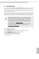
FM2A58M-VG3+ R2.0 1. Introduction Thank you for purchasing ASRock FM2A58M-VG3+ R2.0 motherboard, a reliable motherboard produced under ASRock’s consistently stringent quality control. It delivers excellent performance with robust design conforming to ASRock’s commitment to quality and endurance. In this documentation, Chapter 1 and 2 contains the introduction of the motherboard and step-by-step installation guides. Chapter 3 contains the operation guide of the software and utilities.
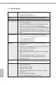
1.2 Speciications Platform CPU Chipset Memory Expansion Slot Graphics Audio LAN English 2 - Micro ATX Form Factor - All Solid Capacitor design - High Density Glass Fabric PCB - Supports Socket FM2+ 95W / FM2 100W processors - AMD A58 FCH (Bolton-D2) - Dual Channel DDR3 Memory Technology - 2 x DDR3 DIMM Slots - Supports DDR3 2400+(OC)/2133/1866/1600/1333/1066 non-ECC, un-buffered memory (see CAUTION 1) - Max.
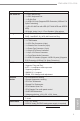
FM2A58M-VG3+ R2.0 Storage Connector BIOS Feature Hardware Monitor OS Certiications - Supports PXE - 1 x PS/2 Mouse Port - 1 x PS/2 Keyboard Port - 1 x D-Sub Port - 4 x USB 2.0 Ports (Supports ESD Protection (ASRock Full Spike Protection)) - 1 x RJ-45 LAN Port with LED (ACT/LINK LED and SPEED LED) - HD Audio Jacks: Line in / Front Speaker / Microphone - 4 x SATA2 3.
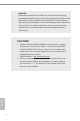
WARNING Please realize that there is a certain risk involved with overclocking, including adjusting the setting in the BIOS, applying Untied Overclocking Technology, or using third-party overclocking tools. Overclocking may affect your system’s stability, or even cause damage to the components and devices of your system. It should be done at your own risk and expense. We are not responsible for possible damage caused by overclocking. CAUTION! 1.
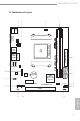
FM2A58M-VG3+ R2.0 1.3 Motherboard Layout PS2 Mouse PS2 Keyboard CPU_FAN1 SATA_4 SATA_3 TPMS1 FSB800 DDR3_B1 (64 bit, 240-pin module) Center: FRONT Top: LINE IN Bottom: MIC IN LAN FM2A58M-VG3+ RJ-45 LAN USB 2.0 T: USB2 B: USB3 ATXPWR1 SOCKET FM2b ATX12V1 USB 2.
No. Description English 6 1 Power Fan Connector (PWR_FAN1) 2 ATX 12V Power Connector (ATX12V1) 3 CPU Fan Connector (CPU_FAN1) 4 2 x 240-pin DDR3 DIMM Slots (DDR3_A1, DDR3_B1) 5 ATX Power Connector (ATXPWR1) 6 SATA2 Connector (SATA_3) 7 SATA2 Connector (SATA_4) 8 SATA2 Connector (SATA_1) 9 SATA2 Connector (SATA_2) 10 Chassis Fan Connector (CHA_FAN1) 11 Chassis Speaker Header (SPEAKER1) 12 System Panel Header (PANEL1) 13 Chassis Intrusion Header (CI1) 14 USB 2.
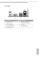
FM2A58M-VG3+ R2.0 1.4 I/O Panel 1 8 7 3 4 6 5 No. Description No. Description 1 PS/2 Mouse Port 6 2 LAN RJ-45 Port* 7 USB 2.0 Ports (USB_0_1) 3 Line In (Light Blue) 8 D-Sub Port 4 Front Speaker (Lime)** 9 PS/2 Keyboard Port 5 Microphone (Pink) USB 2.
* There are two LEDs on the LAN port. Please refer to the table below for the LAN port LED indications. ACT/LINK LED SPEED LED LAN Port Activity / Link LED Speed LED Status Description Status Description Off Blinking On No Link Data Activity Link Off Orange Green 10Mbps connection 100Mbps connection 1Gbps connection To enable Multi-Streaming function, you need to connect a front panel audio cable to the front panel audio header.
FM2A58M-VG3+ R2.0 2. Installation This is a Micro ATX form factor motherboard. Before you install the motherboard, study the coniguration of your chassis to ensure that the motherboard its into it. Pre-installation Precautions Take note of the following precautions before you install motherboard components or change any motherboard settings. Before you install or remove any component, ensure that the power is switched off or the power cord is detached from the power supply.
2.1 CPU Installation Step 1. Unlock the socket by lifting the lever up o to a 90 angle. Step 2. Position the CPU directly above the socket such that the CPU corner with the golden triangle matches the socket corner with a small triangle. Carefully insert the CPU into the socket until it its in place. Step 3. The CPU its only in one correct orientation. DO NOT force the CPU into the socket to avoid bending of the pins. Step 4.
FM2A58M-VG3+ R2.0 2.2 Installation of CPU Fan and Heatsink English After you install the CPU into this motherboard, it is necessary to install a larger heatsink and cooling fan to dissipate heat. You also need to spray thermal grease between the CPU and the heatsink to improve heat dissipation. Make sure that the CPU and the heatsink are securely fastened and in good contact with each other. Then connect the CPU fan to the CPU FAN connector (CPU_FAN1, see Page 5, No. 3).
2.3 Installation of Memory Modules (DIMM) This motherboard provides two 240-pin DDR3 (Double Data Rate 3) DIMM slots, and supports Dual Channel Memory Technology. 1. For dual channel coniguration, you always need to install identical (the same brand, speed, size and chip-type) DDR3 DIMM pairs. 2. It is unable to activate Dual Channel Memory Technology with only one memory module installed. 3.
FM2A58M-VG3+ R2.
2.4 Expansion Slots (PCI Express Slots) There are 2 PCI Express slots on this motherboard. Before installing an expansion card, please make sure that the power supply is switched off or the power cord is unplugged. Please read the documentation of the expansion card and make necessary hardware settings for the card before you start the installation. PCIE Slot: PCIE1 (PCIe 2.0 x1 slot) is used for PCI Express cards with x1 lane width cards. PCIE2 (PCIe 3.
FM2A58M-VG3+ R2.0 2.5 Jumpers Setup The illustration shows how jumpers are setup. When the jumper cap is placed on pins, the jumper is “Short”. If no jumper cap is placed on pins, the jumper is “Open”. The illustration shows a 3-pin jumper whose pin1 and pin2 are “Short” when jumper cap is placed on these 2 pins. Jumper Clear CMOS Jumper Setting Description (CLRCMOS1) (see p.5, No. 15) Default Clear CMOS Note: CLRCMOS1 allows you to clear the data in CMOS.
2.6 Onboard Headers and Connectors Onboard headers and connectors are NOT jumpers. Do NOT place jumper caps over these headers and connectors. Placing jumper caps over the headers and connectors will cause permanent damage of the motherboard! These four Serial ATA2 SATA_3 (SATA_1: see p.5, No. 8) (SATA_2: see p.5, No. 9) SATA_4 Serial ATA2 Connectors (SATA2) connectors support SATA data cables for internal SATA2 interface allows up to 3.0 Gb/s data transfer rate. SATA_2 storage devices.
FM2A58M-VG3+ R2.0 C. Connect Ground (GND) to Ground (GND). D. MIC_RET and OUT_RET are for HD audio panel only. You don’t need to connect them for AC’97 audio panel. E. To activate the front mic. For Windows® 8.1 / 8.1 64-bit / 7 / 7 64-bit 64-bit OS: Go to the "FrontMic" Tab in the Realtek Control panel. Adjust “Recording Volume”. System Panel Header PLED+ PLEDPWRBTN# GND (9-pin PANEL1) This header accommodates several system front panel functions. (see p.5 No.
Chassis Speaker Header DUMMY SPEAKER Please connect the chassis (4-pin SPEAKER 1) 1 speaker to this header. (see p.5 No. 11) +5V DUMMY Chassis and Power Fan Connectors Please connect the fan cables (4-pin CHA_FAN1) to the fan connectors and (see p.5 No. 10) match the black wire to the ground pin. CHA_FAN1 fan speed can be controlled through (3-pin PWR_FAN1) FAN_SPEED +12V GND (see p.5 No. 1) CPU Fan Connectors (4-pin CPU_FAN1) UEFI or A-Tuning.
FM2A58M-VG3+ R2.0 Chassis Intrusion Header (see p.5, No. 13) This motherboard supports 1 CASE OPEN detection feature GND Signal that detects if the chassis cover has been removed. This feature requires a chassis with chassis intrusion detection design. TPM Header (17-pin TPMS1) (see p.5, No. 18) PCIRST# FRAME PCICLK This connector supports Trusted Platform Module (TPM) system, which can securely store keys, digital certiicates, passwords, and data.
2.7 AMD Dual Graphics Operation Guide This motherboard supports AMD Dual Graphics feature. AMD Dual Graphics brings multi-GPU performance capabilities by enabling an AMD A58 FCH (Bolton-D2) integrated graphics processor and a discrete graphics processor to operate simultaneously with combined output to a single display for blisteringly-fast frame rates. Currently, AMD Dual Graphics Technology is only supported with Windows® 8.1 / 7 OS.
FM2A58M-VG3+ R2.0 Step 7. You can also click “AMD VISION Engine Control Center” on your Windows® taskbar to enter AMD VISION Engine Control Center. AMD VISION Engine Control Center Step 8. In AMD VISION Engine Control Center, please choose “Performance”. Click “AMD CrossFireTM”. Step 9. Click “Enable CrossFireTM” and click “Apply“ to save your change. Step 10. Reboot your system. Then you can freely enjoy the beneit of Dual Graphics feature.
3. Software and Utilities Operation 3.1 Installing Drivers The Support CD that comes with the motherboard contains necessary drivers and useful utilities that enhance the motherboard’s features. Running The Support CD To begin using the support CD, insert the CD into your CD-ROM drive. The CD automatically displays the Main Menu if “AUTORUN” is enabled in your computer. If the Main Menu does not appear automatically, locate and double click on the ile “ASRSETUP.EXE” in the Support CD to display the menu.
FM2A58M-VG3+ R2.0 3.2 A-Tuning A-Tuning is ASRock’s multi purpose software suite with a new interface, more new features and improved utilities, including XFast RAM, Dehumidiier, Good Night LED, FAN-Tastic Tuning, OC Tweaker and a whole lot more. 3.2.1 Installing A-Tuning When you install the all-in-one driver to your system from ASRock’s support CD, A-Tuning will be auto-installed as well. After the installation, you will ind the icon “A-Tuning“ on your desktop.
Tools Various tools and utilities. XFast RAM Boost the system’s performance and extend the HDD’s or SDD’s lifespan! Create a hidden partition, then assign which iles should be stored in the RAM drive. *This function supports Windows ® 64-bit OS only. XFast LAN Boost the speed of your internet connection! Select a speciic mode for making the designated program's priority highest. Fast Boot Fast Boot minimizes your computer's boot time. Please note that Ultra Fast mode is only supported by Windows 8.
FM2A58M-VG3+ R2.0 FAN-Tastic Tuning Conigure up to ive different fan speeds using the graph. The fans will automatically shift to the next speed level when the assigned temperature is met. Dehumidiier Prevent motherboard damages due to dampness. Enable this function and conigure the period of time until the computer powers on, and the duration of the dehumidifying process.
OC Tweaker Conigurations for overclocking the system. System Info View information about the system. *The System Browser tab may not appear for certain models.
FM2A58M-VG3+ R2.0 Live Update Check for newer versions of BIOS or drivers. Tech Service English Contact Tech Service if you have problems with your computer. Please leave your contact information along with details of the problem.
Settings Conigure ASRock A-Tuning. Click to select "Auto run at Windows Startup" if you want A-Tuning to be launched when you start up the Windows operating system.
FM2A58M-VG3+ R2.0 3.3 ASRock APP Shop The ASRock APP Shop is an online store for purchasing and downloading software applications for your ASRock computer. You can install various apps and support utilities quickly and easily, and optimize your system and keep your motherboard up to date simply with a few clicks. Double-click on your desktop to access ASRock APP Shop utility. *You need to be connected to the Internet to download apps from the ASRock APP Shop. 3.3.
3.3.2 Apps When the "Apps" tab is selected, you will see all the available apps on screen for you to download. Installing an App Step 1 Find the app you want to install. The most recommended app appears on the left side of the screen. The other various apps are shown on the right. Please scroll up and down to see more apps listed. You can check the price of the app and whether you have already intalled it or not. - The red icon displays the price or "Free" if the app is free of charge.
FM2A58M-VG3+ R2.0 Step 3 If you want to install the app, click on the red icon downloading. to start Step 4 To uninstall it, simply click on the trash can icon *The trash icon may not appear for certain apps. English When installation completes, you can ind the green "Installed" icon appears on the upper right corner. .
Upgrading an App You can only upgrade the apps you have already installed. When there is an available new version for your app, you will ind the mark of "New Version" appears below the installed app icon. Step 1 Click on the app icon to see more details. Step 2 Click on the yellow icon English 32 to start upgrading.
FM2A58M-VG3+ R2.0 3.3.3 BIOS & Drivers Installing BIOS or Drivers When the "BIOS & Drivers" tab is selected, you will see a list of recommended or critical updates for the BIOS or drivers. Please update them all soon. Step 1 Please check the item information before update. Click on details. to see more Step 2 Click to select one or more items you want to update. Step 3 English Click Update to start the update process.
3.3.4 Setting In the "Setting" page, you can change the language, select the server location, and determine if you want to automatically run the ASRock APP Shop on Windows startup.
FM2A58M-VG3+ R2.0 3.4 Start8 For those Windows 8 users who miss the Start Menu, Start8 is an ideal solution that brings back the familiar Start Menu along with added customizations for greater eficiency. 3.4.1 Installing Start8 Install Start8,, which is located in the folder at the following path of the Support CD: \ ASRock Utility > Start8. 3.4.2 Coniguring Start8 Style English Select between the Windows 7 style and Windows 8 style Start Menu.
Conigure Conigure provides coniguration options, including icon sizes, which shortcuts you want Start Menu to display, quick access to recently used apps, the functionality of the power button, and more.
FM2A58M-VG3+ R2.0 Control lets you conigure what a click on the start button or a press on the Windows key does. Desktop Desktop allows you to disable the hot corners when you are working on the desktop. It also lets you choose whether or not the system boots directly into desktop mode and bypass the Metro user interface. About English Displays information about Start8.
4. UEFI SETUP UTILITY 4.1 Introduction ASRock Interactive UEFI is a blend of system coniguration tools, cool sound effects and stunning visuals. Not only will it make BIOS setup less dificult but also a lot more amusing. This section explains how to use the UEFI SETUP UTILITY to conigure your system. The UEFI chip on the motherboard stores the UEFI SETUP UTILITY. You may run the UEFI SETUP UTILITY when you start up the computer.
FM2A58M-VG3+ R2.0 4.1.2 Navigation Keys Please check the following table for the function description of each navigation key.
4.3 OC Tweaker Screen In the OC Tweaker screen, you can set up overclocking features. EZ OC Mode You can use this option to adjust EZ overclocking setting. Please note that overclocing may cause damage to your components and motherboard. It should be done at your own risk and expense. English CPU Coniguration Overclock Mode Use this to select Overclock Mode. Configuration options: [Auto] and [Manual]. The default value is [Auto].
FM2A58M-VG3+ R2.0 Processor Maximum Frequency It will display Processor Maximum Frequency for reference. Processor Maximum Voltage It will display Processor Maximum Voltage for reference. Multiplier/Voltage Change This item is set to [Auto] by default. If it is set to [Manual], you may adjust the value of Processor Frequency and Processor Voltage. However, it is recommended to keep the default value for system stability.
DRAM Timing Control DRAM Slot Use this item to view SPD data. DRAM Timing Control Use this item to control DRAM timing. Power Down Enable Use this item to enable or disable DDR power down mode. Bank Interleaving Interleaving allows memory accesses to be spread out over banks on the same node, or accross nodes, decreasing access contention. Channel Interleaving It allows you to enable Channel Memory Interleaving. Coniguration options: [Disabled], [Auto]. The default value is [Auto].
FM2A58M-VG3+ R2.0 4.4 Advanced Screen In this section, you may set the conigurations for the following items: CPU Coniguration, Nouth Bridge Coniguration, South Bridge Coniguration, Storage Coniguration, ACPI Coniguration, USB Coniguration and Trusted Computing. English Setting wrong values in this section may cause the system to malfunction.
4.4.1 CPU Coniguration Core C6 Mode Use this item to enable or disable Core C6 mode. The default value is [Enabled]. Package C6 Mode This item appears only when you enable the item “Core C6 Mode”. Use this item to enable or disable Package C6 mode. The default value is [Disabled]. Cool ‘n’ Quiet Use this item to enable or disable AMD’s Cool ‘n’ QuietTM technology. The default value is [Enabled]. Coniguration options: [Enabled] and [Disabled]. If you install Windows® 8.
FM2A58M-VG3+ R2.0 4.4.2 North Bridge Coniguration English IOMMU This allows you to enable or disable IOMMU support. Primary Graphics Adapter This item will switch the PCI Bus scanning order while searching for video card. It allows you to select the type of Primary VGA in case of multiple video controllers. The default value of this feature is [PCI Express]. Coniguration options: [Onboard] and [PCI Express]. Share Memory This allows you to set the share memory feature. The default value is [Auto].
4.4.3 South Bridge Coniguration Onboard HD Audio Select [Auto], [Enabled] or [Disabled] for the onboard HD Audio feature. If you select [Auto], the onboard HD Audio will be disabled when PCI Sound Card is plugged. Front Panel Select [Auto] or [Disabled] for the onboard HD Audio Front Panel. Onboard LAN This allows you to enable or disable the onboard LAN feature. Good Night LED Enable this option to turn off Power LED when the system is power on. The keyboard LED will also be turned off in S3 and S4 state.
FM2A58M-VG3+ R2.0 4.4.4 Storage Coniguration English SATA Controller Use this item to enable or disable the “SATA Controller” feature. SATA Mode Use this item to adjust SATA Mode. The default value of this option is [AHCI Mode]. Coniguration options: [AHCI Mode], [RAID Mode] and [IDE Mode]. AMD AHCI BIOS ROM Use this item to enable or disable AMD AHCI BIOS ROM. The default value of this option is [Disabled]. SATA IDE Combined Mode Use this item to enable or disable SATA IDE combined mode.
4.4.5 ACPI Coniguration Suspend to RAM Use this item to select whether to auto-detect or disable the Suspend-toRAM feature. Select [Auto] will enable this feature if the OS supports it. Check Ready Bit Enable to enter the operating system after S3 only when the hard disk is ready, this is recommended for better system stability. English Deep Sleep Conigure deep sleep mode for power saving when the computer is shut down. We recommend disabling Deep Sleep for better system compatibility and stability.
FM2A58M-VG3+ R2.0 USB Keyboard/Remote Power On Use this item to enable or disable USB Keyboard/Remote to power on the system. USB Mouse Power On Use this item to enable or disable USB Mouse to power on the system. English ACPI HPET table Use this item to enable or disable ACPI HPET Table. The default value is [Enabled]. Please set this option to [Enabled] if you plan to use this motherboard to submit Windows® certiication.
4.4.6 USB Coniguration USB 2.0 Controller Use this item to enable or disable the use of USB 2.0 controller. Legacy USB Support Use this option to select legacy support for USB devices. There are four coni guration options: [Enabled], [Auto], [Disabled] and [UEFI Setup Only]. The default value is [Enabled]. Please refer to below descriptions for the details of these four options: [Enabled] - Enables support for legacy USB. [Auto] - Enables legacy support if USB devices are connected.
FM2A58M-VG3+ R2.0 4.4.7 Trusted Computing English Security Device Support Enable to activate Trusted Platform Module (TPM) security for your hard disk drives.
4.5 Tool OMG(Online Management Guard) Administrators are able to establish an internet curfew or restrict internet access at speciied times via OMG. You may schedule the starting and ending hours of internet access granted to other users. In order to prevent users from bypassing OMG, guest accounts without permission to modify the system time are required. UEFI Tech Service Contact ASRock Tech Service if you are having trouble with your PC. Please setup network coniguration before using UEFI Tech Service.
FM2A58M-VG3+ R2.0 UEFI ile to your USB lash drive, loppy disk or hard drive and launch this tool, then you can update your UEFI only in a few clicks without preparing an additional loppy diskette or other complicated lash utility. Please be noted that the USB lash drive or hard drive must use FAT32/16/12 ile system. If you execute Instant Flash utility, the utility will show the UEFI iles and their respective information.
Dehumidiier Duration This allows users to conigure the duration of the dehumidifying process before it returns to S4/S5 state. Dehumidiier CPU Fan Setting Use this setting to conigure CPU fan speed while “Dehumidiier” is enabled. Would you like to save current setting user defaults? In this option, you are allowed to load and save three user defaults according to your own requirements.
FM2A58M-VG3+ R2.0 4.6 Hardware Health Event Monitoring Screen In this section, it allows you to monitor the status of the hardware on your system, including the parameters of the CPU temperature, motherboard temperature, CPU fan speed, chassis fan speed, and the critical voltage. English CPU Fan 1 Setting This allows you to set the CPU fan 1 speed. Coni guration options: [Full On] and [Automatic Mode]. The default is value [Full On]. Chassis Fan 1 Setting This allows you to set the chassis fan 1 speed.
4.7 Boot Screen In this section, it will display the available devices on your system for you to conigure the boot settings and the boot priority. Fast Boot Fast Boot minimizes your computer’s boot time. There are three coniguration options: [Disabled], [Fast] and [Ultra Fast]. The default value is [Disabled]. Please refer to below descriptions for the details of these three options: [Disabled] - Disable Fast Boot. [Fast] - The only restriction is you may not boot by using an USB lash drive.
FM2A58M-VG3+ R2.0 Option ROM Messages [Force BIOS] - The third-party ROM messages will be forced to display during the bootsequence. [Keep Current] - The third-party ROM messages will be displayed only if the third-partymanufacturer had set the add-on device to do so. Boot Failure Guard Enable or disable the feature of Boot Failure Guard. Boot Failure Guard Count Enable or disable the feature of Boot Failure Guard Count.
4.8 Security Screen In this section, you may set or change the supervisor/user password for the system. For the user password, you may also clear it. Secure Boot Enable to support Windows® 8.1 Secure Boot.
FM2A58M-VG3+ R2.0 4.9 Exit Screen English Save Changes and Exit When you select this option, it will pop-out the following message, “Save coniguration changes and exit setup?” Select [OK] to save the changes and exit the UEFI SETUP UTILITY. Discard Changes and Exit When you select this option, it will pop-out the following message, “Discard changes and exit setup?” Select [OK] to exit the UEFI SETUP UTILITY without saving any changes.
Contact Information If you need to contact ASRock or want to know more about ASRock, you’re welcome to visit ASRock’s website at http://www.asrock.com; or you may contact your dealer for further information. For technical questions, please submit a support request form at http://www.asrock.com/support/tsd.asp ASRock Incorporation 2F., No.37, Sec. 2, Jhongyang S. Rd., Beitou District, Taipei City 112, Taiwan (R.O.C.) ASRock EUROPE B.V.