Version 1.0 Published September 2014 Copyright©2014 ASRock INC. All rights reserved. Copyright Notice: No part of this documentation may be reproduced, transcribed, transmitted, or translated in any language, in any form or by any means, except duplication of documentation by the purchaser for backup purpose, without written consent of ASRock Inc.
he terms HDMI™ and HDMI High-Deinition Multimedia Interface, and the HDMI logo are trademarks or registered trademarks of HDMI Licensing LLC in the United States and other countries. Manufactured under license under U.S. Patent Nos: 5,956,674; 5,974,380; 6,487,535; 7,003,467 & other U.S. and worldwide patents issued & pending. DTS, the Symbol, & DTS and the Symbol together is a registered trademark & DTS Connect, DTS Interactive, DTS Neo:PC are trademarks of DTS, Inc. Product includes sotware. © DTS, Inc.
Fatal1ty Story Who knew that at age 19, I would be a World Champion PC gamer. When I was 13, I actually played competitive billiards in professional tournaments and won four or ive games of guys who played at the highest level. I actually thought of making a career of it, but at that young age situations change rapidly. Because I’ve been blessed with great hand-eye coordination and a grasp of mathematics (an important element in video gaming) I gravitated to that activity.
LIVIN’ LARGE Since my irst big tournament wins, I have been a “Professional Cyberathlete”, traveling the world and livin’ large with lots of International media coverage on outlets such as MTV, ESPN and a 60 Minutes segment on CBS to name only a few. It's unreal - it's crazy. I’m living a dream by playing video games for a living. I’ve always been athletic and took sports like hockey and football very seriously, working out and training hard.
Contents Chapter 1 Introduction 1 1.1 Package Contents 1 1.2 Speciications 2 1.3 Motherboard Layout 7 1.4 I/O Panel 9 Chapter 2 Installation 11 2.1 Installing the CPU 12 2.2 Installing the CPU Fan and Heatsink 15 2.3 Installing Memory Modules (DIMM) 16 2.4 Expansion Slots (PCI Express Slots) 18 2.5 Jumpers Setup 19 2.6 Onboard Headers and Connectors 20 2.7 SLITM and Quad SLITM Operation Guide 25 2.7.1 Installing Two SLITM-Ready Graphics Cards 25 2.7.
3.2 F-Stream 35 3.2.1 Installing F-Stream 35 3.2.2 Using F-Stream 35 3.3 41 Killer Network Manager 3.3.1 Installing Killer Network Manager 41 3.3.2 Using Killer Network Manager 41 3.4 44 Intel® Rapid Start Technology 3.4.1 System Requirements 44 3.4.2 Setup Guide 45 3.5 49 Intel® Smart Connect Technology 3.5.1 System Requirements 49 3.5.2 Setup Guide 50 3.6 54 ASRock APP Shop 3.6.1 UI Overview 54 3.6.2 Apps 55 3.6.3 BIOS & Drivers 58 3.6.4 Setting 59 3.
Chapter 4 UEFI SETUP UTILITY 67 4.1 Introduction 67 4.1.1 UEFI Menu Bar 67 4.1.2 Navigation Keys 68 4.2 Main Screen 69 4.3 OC Tweaker Screen 70 4.4 Advanced Screen 79 4.4.1 CPU Coniguration 80 4.4.2 Chipset Coniguration 82 4.4.3 Storage Coniguration 85 4.4.4 Intel® Rapid Start Technology 87 4.4.5 Intel® Smart Connect Technology 88 4.4.6 Intel® Thunderbolt 89 4.4.7 Super IO Coniguration 90 4.4.8 ACPI Coniguration 91 4.4.9 USB Coniguration 93 4.4.
Fatal1ty Z97M Killer Series Chapter 1 Introduction hank you for purchasing ASRock Fatal1ty Z97M Killer Series motherboard, a reliable motherboard produced under ASRock’s consistently stringent quality control. It delivers excellent performance with robust design conforming to ASRock’s commitment to quality and endurance. In this documentation, Chapter 1 and 2 contains the introduction of the motherboard and step-by-step installation guides.
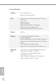
1.2 Speciications English 2 Platform • Micro ATX Form Factor • High Density Glass Fabric PCB CPU • Supports 4th Gen & 5th Generation Intel® CoreTM Processors (Socket 1150) • Digi Power design • 8 Power Phase design • Supports Intel® Turbo Boost 2.
Fatal1ty Z97M Killer Series • Intel® HD Graphics Built-in Visuals and the VGA outputs can be supported only with processors which are GPU integrated. • Supports Intel® HD Graphics Built-in Visuals : Intel® Quick Sync Video with AVC, MVC (S3D) and MPEG-2 Full HW Encode1, Intel® InTruTM 3D, Intel® Clear Video HD Technology, Intel® InsiderTM, Intel® HD Graphics 4400/4600 • • • • • • • • • • Audio Pixel Shader 5.0, DirectX 11.1 Max.
LAN • PCIE x1 Gigabit LAN 10/100/1000 Mb/s • Qualcomm® Atheros® KillerTM E2200 Series • Supports Qualcomm® Atheros® Security Wake On Internet Technology • Supports Wake-On-LAN • Supports Lightning/ESD Protection (ASRock Full Spike Protection) • Supports Energy Eicient Ethernet 802.3az • Supports PXE Rear Panel I/O • • • • • • • • • • • Storage English 4 1 x PS/2 Mouse/Keyboard Port 1 x D-Sub Port 1 x DVI-D Port 1 x HDMI Port 1 x Optical SPDIF Out Port 1 x eSATA Connector 3 x USB 2.
Fatal1ty Z97M Killer Series Connector • • • • • • 1 x COM Port Header 1 x Chassis Intrusion Header 1 x TPM Header 1 x Power LED header 2 x CPU Fan Connectors (1 x 4-pin, 1 x 3-pin) 2 x Chassis Fan Connectors (1 x 4-pin, 1 x 3-pin) • 1 x Power Fan Connector (3-pin) • 1 x 24 pin ATX Power Connector • 1 x 8 pin 12V Power Connector (Hi-Density Power Connector) • 1 x PCIe Power Connector • 1 x Front Panel Audio Connector • 1 x hunderbolt AIC Connector • 2 x USB 2.0 Headers (Support 4 USB 2.
* For detailed product information, please visit our website: http://www.asrock.com Please realize that there is a certain risk involved with overclocking, including adjusting the setting in the BIOS, applying Untied Overclocking Technology, or using third-party overclocking tools. Overclocking may afect your system’s stability, or even cause damage to the components and devices of your system. It should be done at your own risk and expense.
Fatal1ty Z97M Killer Series 1.3 Motherboard Layout 1 USB 2.0 T: USB0 B:USB1 3 CPU_FAN2 CPU_FAN1 5 4 ATX12V1 ATXPWR1 USB 2.0 T: USB2 B: USB3 DDR3_B1 (64 bit, 240-pin module) USB 3.
No. Description English 8 1 ATX 12V Power Connector (ATX12V1) 2 CPU Fan Connector (CPU_FAN2) 3 CPU Fan Connector (CPU_FAN1) 4 2 x 240-pin DDR3 DIMM Slots (DDR3_A1, DDR3_B1) 5 2 x 240-pin DDR3 DIMM Slots (DDR3_A2, DDR3_B2) 6 ATX Power Connector (ATXPWR1) 7 USB 3.
Fatal1ty Z97M Killer Series 1.4 I/O Panel 7 9 2 3 4 5 6 8 10 17 16 15 14 13 12 11 1 No. Description No. Description 1 Fatal1ty Mouse Port (USB0) 10 Front Speaker (Lime)** 2 USB 2.0 Port (USB1) 11 Microphone (Pink) 3 D-Sub Port 12 Optical SPDIF Out Port 4 USB 3.0 Ports (USB3_01) 13 USB 3.0 Ports (USB3_23) 5 USB 2.
* here are two LEDs on each LAN port. Please refer to the table below for the LAN port LED indications. ACT/LINK LED SPEED LED LAN Port Activity / Link LED Speed LED Status Description Status Description Of Blinking On No Link Data Activity Link Of Orange Green 10Mbps connection 100Mbps connection 1Gbps connection ** If you use a 2-channel speaker, please connect the speaker’s plug into “Front Speaker Jack”.
Fatal1ty Z97M Killer Series Chapter 2 Installation his is a Micro ATX form factor motherboard. Before you install the motherboard, study the coniguration of your chassis to ensure that the motherboard its into it. Pre-installation Precautions Take note of the following precautions before you install motherboard components or change any motherboard settings. English • Make sure to unplug the power cord before installing or removing the motherboard components.
2.1 Installing the CPU 1. Before you insert the 1150-Pin CPU into the socket, please check if the PnP cap is on the socket, if the CPU surface is unclean, or if there are any bent pins in the socket. Do not force to insert the CPU into the socket if above situation is found. Otherwise, the CPU will be seriously damaged. 2. Unplug all power cables before installing the CPU.
Fatal1ty Z97M Killer Series 4 3 English 5 13
Please save and replace the cover if the processor is removed. he cover must be placed if you wish to return the motherboard for ater service.
Fatal1ty Z97M Killer Series 2.
2.3 Installing Memory Modules (DIMM) his motherboard provides four 240-pin DDR3 (Double Data Rate 3) DIMM slots, and supports Dual Channel Memory Technology. 1. For dual channel coniguration, you always need to install identical (the same brand, speed, size and chip-type) DDR3 DIMM pairs. 2. It is unable to activate Dual Channel Memory Technology with only one or three memory module installed. 3.
Fatal1ty Z97M Killer Series 1 2 English 3 17
2.4 Expansion Slots (PCI Express Slots) here are 4 PCI Express slots on the motherboard. Before installing an expansion card, please make sure that the power supply is switched of or the power cord is unplugged. Please read the documentation of the expansion card and make necessary hardware settings for the card before you start the installation. PCIe slots: PCIE1 (PCIe 3.0 x16 slot) is used for PCI Express x16 lane width graphics cards. PCIE2 (PCIe 2.
Fatal1ty Z97M Killer Series 2.5 Jumpers Setup he illustration shows how jumpers are setup. When the jumper cap is placed on the pins, the jumper is “Short”. If no jumper cap is placed on the pins, the jumper is “Open”. he illustration shows a 3-pin jumper whose pin1 and pin2 are “Short” when a jumper cap is placed on these 2 pins. Clear CMOS Jumper (CLRMOS1) (see p.7, No. 15) Default Clear CMOS English CLRMOS1 allows you to clear the data in CMOS.
2.6 Onboard Headers and Connectors Onboard headers and connectors are NOT jumpers. Do NOT place jumper caps over these headers and connectors. Placing jumper caps over the headers and connectors will cause permanent damage to the motherboard. System Panel Header (9-pin PANEL1) (see p.7, No. 18) PLED+ PLEDPWRBTN# GND 1 GND RESET# GND HDLEDHDLED+ Connect the power switch, reset switch and system status indicator on the chassis to this header according to the pin assignments below.
Fatal1ty Z97M Killer Series SATAE_1 Serial ATA Express Connector (SATAE_1) (see p.7, No. 14) Please connect the chassis power LED to this header to indicate the system’s power status. hese six SATA3 connectors support SATA data cables for internal storage devices with up to 6.0 Gb/s data transfer rate. he SATA3_4, SATA3_5 are shared with the SATA Express connector. he SATA3_1 is shared with the eSATA1 port on the I/O panel.. Please connect either SATA or PCIe storage devices to this connector.
USB_PWR PP+ USB 2.0 Headers (9-pin USB4_5) (see p.7, No. 22) (9-pin USB6_7) (see p.7, No. 23) USB 3.0 Header (19-pin USB3_4_5) (see p.7, No. 7) GND DUMMY 1 GND P+ PUSB_PWR Vbus Vbus IntA_PB_SSRX- IntA_PA_SSRX- IntA_PB_SSRX+ GND IntA_PA_SSRX+ IntA_PB_SSTX- GND IntA_PA_SSTX- IntA_PB_SSTX+ IntA_PA_SSTX+ GND IntA_PB_D- GND IntA_PA_D- IntA_PB_D+ IntA_PA_D+ Dummy Besides four USB 2.0 ports on the I/O panel, there are two headers on this motherboard. Each USB 2.0 header can support two ports.
Fatal1ty Z97M Killer Series Chassis and Power Fan Connectors (4-pin CHA_FAN1) (see p.7, No. 19) FAN_SPEED_CONTROL CHA_FAN_SPEED +12V GND (3-pin CHA_FAN2) (see p.7, No. 26) Please connect fan cables to the fan connectors and match the black wire to the ground pin. GND FAN_VOLTAGE CHA_FAN_SPEED (3-pin PWR_FAN1) (see p.7, No. 27) CPU Fan Connectors (4-pin CPU_FAN1) (see p.7, No. 3) 4 3 2 1 GND +12V CPU_FAN_SPEED FAN_SPEED_CONTROL (3-pin CPU_FAN2) (see p.7, No.
hunderbolt AIC Connector (5-pin TB1) (see p.7, No. 16) Serial Port Header (9-pin COM1) (see p.7, No. 25) Please connect a hunderbolt™ add-in card (AIC) to this connector via the GPIO cable. 1 1 his COM1 header supports a serial port module. RRXD1 DDTR#1 DDSR#1 CCTS#1 1 SERIRQ# GND GND LAD0 S_PWRDWN# LAD2 LAD1 +3V SMB_CLK_MAIN SMB_DATA_MAIN PCIRST# LAD3 GND FRAME TPM Header (17-pin TPMS1) (see p.7, No.
Fatal1ty Z97M Killer Series 2.7 SLITM and Quad SLITM Operation Guide his motherboard supports NVIDIA® SLITM and Quad SLITM (Scalable Link Interface) technology that allows you to install up to two identical PCI Express x16 graphics cards. Currently, NVIDIA® SLITM and Quad SLITM technology supports Windows® 7 / 7 64-bit / 8 / 8 64-bit / 8.1 / 8.1 64-bit OS. Requirements 1. You should only use identical SLITM-ready graphics cards that are NVIDIA® certiied. 2.
Step 3 Align and insert the ASRock SLI_Bridge Card to the goldingers on each graphics card. Make sure the ASRock SLI_Bridge Card is irmly in place. ASRock SLI_Bridge Card Step 4 Connect a VGA cable or a DVI cable to the monitor connector or the DVI connector of the graphics card that is inserted to PCIE1 slot.
Fatal1ty Z97M Killer Series 2.7.2 Driver Installation and Setup Install the graphics card drivers to your system. Ater that, you can enable the Multi-Graphics Processing Unit (GPU) in the NVIDIA® nView system tray utility. Please follow the below procedures to enable the multi-GPU. For SLITM and Quad SLITM mode Step 1 Double-click the NVIDIA Control Panel icon in the Windows® system tray. Step 2 In the let pane, click Set SLI and PhysX coniguration. hen select Maximize 3D performance and click Apply.
2.8 CrossFireXTM and Quad CrossFireXTM Operation Guide his motherboard supports CrossFireXTM and Quad CrossFireXTM that allows you to install up to three identical PCI Express x16 graphics cards. Currently CrossFireXTM and Quad CrossFireXTM are supported with Windows® 7 / 7 64-bit / 8 / 8 64-bit / 8.1 / 8.1 64-bit OS. 1. You should only use identical CrossFireXTM-ready graphics cards that are AMD certiied. 2. Make sure that your graphics card driver supports AMD CrossFireXTM technology.
Fatal1ty Z97M Killer Series Step 3 English Connect a VGA cable or a DVI cable to the monitor connector or the DVI connector of the graphics card that is inserted to PCIE2 slot.
2.8.2 Driver Installation and Setup Step 1 Power on your computer and boot into OS. Step 2 Remove the AMD drivers if you have any VGA drivers installed in your system. he Catalyst Uninstaller is an optional download. We recommend using this utility to uninstall any previously installed Catalyst drivers prior to installation. Please check AMD’s website for AMD driver updates. Step 3 Install the required drivers and CATALYST Control Center then restart your computer. Please check AMD’s website for details.
Fatal1ty Z97M Killer Series 2.9 M.2_SSD (NGFF) Module Installation Guide The M.2, also known as the Next Generation Form Factor (NGFF), is a small size and versatile card edge connector that aims to replace mPCIe and mSATA. The M.2_SSD (NGFF) Socket 3 can accommodate either a M.2 SATA3 6.0 Gb/s module or a M.2 PCI Express module up to Gen 2 x2 (10 Gb/s). Please be noted that the M.2_SSD (NGFF) Socket 3 is shared with the SATA Express connector; you can only choose either the M.
Step 3 D C A B Move the standof based on the module type and length. he standof is placed at the nut location D by default. Skip Step 3 and 4 and go straight to Step 5 if you are going to use the default nut. Otherwise, release the standof by hand. Step 4 D C A B Peel of the yellow protective ilm on the nut to be used. Hand tighten the standof into the desired nut location on the motherboard. Step 5 Align and gently insert the M.2 (NGFF) SSD module into the M.2 slot. Please be aware that the M.
Fatal1ty Z97M Killer Series M.2_SSD (NGFF) Module Support List PCIe Interface SATA Interface Plextor PX-G512M6e ADATA AXNS381E-128GM-B Plextor PX-G256M6e ADATA AXNS381E-256GM-B SanDisk SD6PP4M-128G Crucial CT120M500SSD4/120G SanDisk SD6PP4M-256G Crucial CT240M500SSD4/240G Samsung XP941-512G (MZHPU512HCGL) Intel SSDSCKGW080A401/80G Kingston RBU-SM2280S3/120G English For the latest updates of M.2_SSD (NFGG) module support list, please visit our website for details: http://www.asrock.
Chapter 3 Software and Utilities Operation 3.1 Installing Drivers he Support CD that comes with the motherboard contains necessary drivers and useful utilities that enhance the motherboard’s features. Running The Support CD To begin using the support CD, insert the CD into your CD-ROM drive. he CD automatically displays the Main Menu if “AUTORUN” is enabled in your computer. If the Main Menu does not appear automatically, locate and double click on the ile “ASRSETUP.
Fatal1ty Z97M Killer Series 3.2 F-Stream F-Stream is ASRock’s multi purpose sotware suite with a new interface, more new features and improved utilities, including XFast RAM, Dehumidiier, Good Night LED, FAN-Tastic Tuning, OC Tweaker and a whole lot more. 3.2.1 Installing F-Stream When you install the all-in-one driver to your system from ASRock’s support CD, F-Stream will be auto-installed as well. Ater the installation, you will ind the icon “F-Stream“ on your desktop.
Tools Various tools and utilities. XFast RAM Boost the system’s performance and extend the HDD’s or SDD’s lifespan! Create a hidden partition, then assign which iles should be stored in the RAM drive. Fast Boot Fast Boot minimizes your computer's boot time. Please note that Ultra Fast mode is only supported by Windows 8.1/8 and the VBIOS must support UEFI GOP if you are using an external graphics card. OMG Schedule the starting and ending hours of Internet access granted to other users.
Fatal1ty Z97M Killer Series Dehumidiier Prevent motherboard damages due to dampness. Enable this function and conigure the period of time until the computer powers on, and the duration of the dehumidifying process. Key Master Enhance your mouse and keyboard with customizable macros, sniper modes, scroll speed, key repeat rates and repeat delay. Fata1ty Mouse Port You are installing the mouse into Fata1ty Mouse Port.
OC Tweaker Conigurations for overclocking the system. System Info View information about the system.
Fatal1ty Z97M Killer Series System Browser System Browser shows the overview of your current PC and the devices connected. Hardware Monitor Shows the major readings of your system. Live Update English Check for newer versions of BIOS or drivers.
Tech Service Contact Tech Service if you have problems with your computer. Please leave your contact information along with details of the problem. Settings Conigure ASRock F-Stream. Click to select "Auto run at Windows Startup" if you want F-Stream to be launched when you start up the Windows operating system.
Fatal1ty Z97M Killer Series 3.3 Killer Network Manager Qualcomm® Atheros® Killer Network Manager allows you to control the upload and download speeds for online applications accessing your network resources, as well as allowing you to customize priority and bandwidth for all network traic to it your needs. 3.3.1 Installing Killer Network Manager When you install the all-in-one driver to your system from ASRock’s support CD, Killer Network Manager will be auto-installed as well.
Performance Performance allows you to view in real time your system performance and current network utilization for download and upload traic. Network Network allows you to set your preferred upload/download speeds and test the network speed. * You must have Adobe Flash Player installed to run the network speed test.
Fatal1ty Z97M Killer Series Killer Ethernet English Killer Ethernet displays the network information.
3.4 Intel® Rapid Start Technology Intel® Rapid Start Technology enables your system to wake up faster from deep sleep, saving time and power consumption. Feel secure to know that your system will resume to working condition even if an unexpected power loss happens while the PC is in sleep mode. 3.4.1 System Requirements • Conirm whether your motherboard supports this feature. • Operating system: Microsot Windows 8.1/8/7 (32- or 64-bit edition) • Set the SATA mode to AHCI. If Windows 8.
Fatal1ty Z97M Killer Series 3. Exit the Registry Editor window and restart the computer. 4. Press F2 to enter BIOS, then go to Advanced ‐> Storage Coniguration and change SATA Mode to AHCI. Press F10 to save changes and exit. 5. Enter Windows 8.1/8/7. Windows will discover the new device and install AHCI drivers automatically. 3.4.2 Setup Guide Coniguring Rapid Start Step 1 Run ASRock Rapid Start utility from Start -> All Programs -> ASRock Utility.
Step 3 When prompted to restart ater the setup, click Yes to reboot. Step 4 Double-click the Intel® Rapid Start Technology Manager icon system tray.
Fatal1ty Z97M Killer Series Step 5 Make sure Rapid Start is on. Drag the slider to conigure the time. For example, if the timer value is set to ten minutes, the system will enable Rapid Start mode ater entering sleep state for ten minutes. If the timer is set to 0 minutes, Windows will immediately enable Rapid Start mode as it enters sleep state. 1. You may shut down the computer without terminating the applications or iles you are executing currently.
state for a period of time. he power of the computer in Rapid Start mode can be cut of, it will not cause data loss of the programs or iles you were executing before entering sleep state. 4. English 48 When you wish to continue to use the computer just hit the power button, the system will rapidly return to Windows, the programs and iles which you were using before entering sleep state will be accessible immediately.
Fatal1ty Z97M Killer Series 3.5 Intel® Smart Connect Technology Intel® Smart Connect Technology is a feature that periodically wakes your computer from Windows® sleep state to refresh email or social networking applications. It saves your waiting time and keeps the content always up-to-date. 3.5.1 System Requirements • Conirm whether your motherboard supports this feature. • Operating system: Microsot Windows 8.18/7 (32- or 64-bit edition) • Set the SATA mode to AHCI. If Windows 8.
3.5.2 Setup Guide Installing ASRock Smart Connect Utility Step 1 Install ASRock Smart Connect Utility, which is located in the folder at the following path of the Support CD: \ ASRock Utility > Smart Connect. Step 2 Once installed, run ASRock Smart Connect from your desktop or go to Windows Start -> All Programs -> ASRock Utility.
Fatal1ty Z97M Killer Series Step 3 Click the Add button. Take Foxmail as an example, add Foxmail to the Application list. Step 4 Select Foxmail from the Application List, then click the arrow pointing right to add this application to the Smart Connect List. English Step 5 Click Apply to enable Smart Connect.
Step 6 Double-click the Intel® Smart Connect Technology Manager icon in the Windows system tray. Step 7 Drag the slider to conigure how oten the system will connect to the network to download updates. Shorter durations will provide more frequent updates, but may cause more power consumption. Using Smart Connect Keep the applications which you wish to connect to the internet and receive updates while the system is in sleep state running. Foxmail for instance, keep Foxmail running. 2.
4. he system will wake up from sleep state periodically, and then start to update Foxmail. he screen will not display anything so the computer can maintain minimum power usage. Aterwards, the system will automatically return to sleep state again. 5. Upon waking up the system, you will ind the new mail that were sent to you during sleep state are already updated and ready to be read in Foxmail.
3.6 ASRock APP Shop he ASRock APP Shop is an online store for purchasing and downloading sotware applications for your ASRock computer. You can install various apps and support utilities quickly and easily, and optimize your system and keep your motherboard up to date simply with a few clicks. Double-click on your desktop to access the ASRock APP Shop utility. *You need to be connected to the Internet to download apps from the ASRock APP Shop. 3.6.
Fatal1ty Z97M Killer Series 3.6.2 Apps When the "Apps" tab is selected, you will see all the available apps on screen for you to download. Installing an App Step 1 Find the app you want to install. he most recommended app appears on the let side of the screen. he other various apps are shown on the right. Please scroll up and down to see more apps listed. You can check the price of the app and whether you have already intalled it or not.
Step 3 to start downloading. If you want to install the app, click on the red icon Step 4 When installation completes, you can ind the green "Installed" icon appears on the upper right corner. English To uninstall it, simply click on the trash can icon *he trash icon may not appear for certain apps. 56 .
Fatal1ty Z97M Killer Series Upgrading an App You can only upgrade the apps you have already installed. When there is an available new version for your app, you will ind the mark of "New Version" appears below the installed app icon. Step 1 Click on the app icon to see more details. Step 2 to start upgrading.
3.6.3 BIOS & Drivers Installing BIOS or Drivers When the "BIOS & Drivers" tab is selected, you will see a list of recommended or critical updates for the BIOS or drivers. Please update them all soon. Step 1 Please check the item information before update. Click on Step 2 Click to select one or more items you want to update. Step 3 Click Update to start the update process. English 58 to see more details.
Fatal1ty Z97M Killer Series 3.6.4 Setting English In the "Setting" page, you can change the language, select the server location, and determine if you want to automatically run the ASRock APP Shop on Windows startup.
3.7 Start8 For those Windows 8.1/8 users who miss the Start Menu, Start8 is an ideal solution that brings back the familiar Start Menu along with added customizations for greater eiciency. 3.7.1 Installing Start8 Install Start8, which is located in the folder at the following path of the Support CD: \ ASRock Utility > Start8. 3.7.2 Coniguring Start8 Style Select between the Windows 7 style and Windows 8.1/8 style Start Menu.
Fatal1ty Z97M Killer Series Conigure Conigure provides coniguration options, including icon sizes, which shortcuts you want Start Menu to display, quick access to recently used apps, the functionality of the power button, and more.
Control lets you conigure what a click on the start button or a press on the Windows key does. Desktop Desktop allows you to disable the hot corners when you are working on the desktop. It also lets you choose whether or not the system boots directly into desktop mode and bypass the Metro user interface. About Displays information about Start8.
Fatal1ty Z97M Killer Series 3.8 XSplit Broadcaster XSplit Broadcaster is a desktop application designed to make your multimedia broadcasting, live-streaming and recording a lot easier and more fun to do, we are giving away the 3 months premium license which is worth US$24.95 for free! 3.8.1 Live Streaming Your Gameplay Step 1 Go to Start > All Programs > XSplit > XSplit Broadcaster to launch it. Step 2 English Log in with your own username and password.
Step 3 Go to Broadcast > Add Channels…. Step 4 Click Add.... Step 5 Select a platform for live streaming. *Before you start streaming, you need to register an account for the streaming service website, such as Twitch.tv, USTREAM, or other livestreaming services.
Fatal1ty Z97M Killer Series Step 6 Fill in your platform's Username and Password. Based on your needs, conigure the Video and Audio Encoding settings. Click OK. Step 7 English he channel then appears in your broadcast list. Click Apply and OK to save the settings.
Step 8 Go to Broadcast and select the platform to enable live streaming. A link to view your live Broadcast has been copied for you automatically. Simply press CTRL-V or right click and choose Paste to paste the link into the browser, and you can see your broadcast. To disable live streaming, go to Broadcast again and deselect the platform. 3.8.2 Recording Your Gameplay Step 1 Go to Broadcast > Local recording to start recording.
Fatal1ty Z97M Killer Series Chapter 4 UEFI SETUP UTILITY 4.1 Introduction his section explains how to use the UEFI SETUP UTILITY to conigure your system. You may run the UEFI SETUP UTILITY by pressing or right ater you power on the computer, otherwise, the Power-On-Self-Test (POST) will continue with its test routines. If you wish to enter the UEFI SETUP UTILITY ater POST, restart the system by pressing + + , or by pressing the reset button on the system chassis.
4.1.2 Navigation Keys Use < > key or < > key to choose among the selections on the menu bar, and use < > key or < > key to move the cursor up or down to select items, then press to get into the sub screen. You can also use the mouse to click your required item. Please check the following table for the descriptions of each navigation key.
Fatal1ty Z97M Killer Series 4.2 Main Screen When you enter the UEFI SETUP UTILITY, the Main screen will appear and display the system overview. My Favorite Display your collection of BIOS items. Press F5 to add/remove your favorite items. Active Page on Entry Select the default page when entering the UEFI setup utility. Full HD UEFI When [Auto] is selected, the resolution will be set to 1920 x 1080 if the monitor supports Full HD resolution.
4.3 OC Tweaker Screen In the OC Tweaker screen, you can set up overclocking features. Because the UEFI sotware is constantly being updated, the following UEFI setup screens and descriptions are for reference purpose only, and they may not exactly match what you see on your screen. User OC Proile In this option, you are allowed to load and save ten user defaults according to your own requirements. Advanced Turbo You can use this option to increase your system performance.
Fatal1ty Z97M Killer Series overclocking may cause damage to your GPU and motherboard. It should be done at your own risk and expense. his option appears only when you adopt K-Series CPU. CPU Coniguration Multi Core Enhancement Improve the system's performance by forcing the CPU to perform the highest frequency on all CPU cores simultaneously. Disable to reduce power consumption. CPU Ratio he CPU speed is determined by the CPU Ratio multiplied with the BCLK.
cies and voltage points for better power saving and heat dissipation. Intel Turbo Boost Technology Intel Turbo Boost Technology enables the processor to run above its base operating frequency when the operating system requests the highest performance state. Filter PLL Frequency CPU BCLK Filter Frequency. Choose 1.6 for better overclocking capabilities. Internal PLL Overvoltage Enable for better stability when overclocking. PCIE PLL Selection Use this item to select SB PLL when overclocking.
Fatal1ty Z97M Killer Series Adaptive: Add voltage to the integrated GPU when the system is under heavy load. Override: he voltage is ixed. GT Adaptive Voltage Conigure the ixed voltage added to the integrated GPU. GT Voltage Ofset Conigure the voltage added to the integrated GPU when the system is under heavy load. DRAM Timing Coniguration Load XMP Setting Load XMP settings to overclock the DDR3 memory and perform beyond standard speciications. DRAM Reference Clock Select Auto for optimized settings.
DRAM Tweaker Fine tune the DRAM settings by leaving marks in checkboxes. Click OK to conirm and apply your new settings. CAS# Latency (tCL) he time between sending a column address to the memory and the beginning of the data in response. RAS# to CAS# Delay (tRCD) he number of clock cycles required between the opening of a row of memory and accessing columns within it. Row Precharge Time (tRP) he number of clock cycles required between the issuing of the precharge command and opening the next row.
Fatal1ty Z97M Killer Series he number of clocks between the last valid write operation and the next read command to the same internal bank. Read to Precharge (tRTP) he number of clocks that are inserted between a read command to a row precharge command to the same rank. Four Activate Window (tFAW) he time window in which four activates are allowed the same rank. CAS Write Latency (tCWL) Conigure CAS Write Latency. tREFI Conigure refresh cycles at an average periodic interval.
tWRWRDR Conigure between module write to write delay from diferent ranks. tWRWRDD Conigure between module write to write delay from diferent DIMMs. tRDWR Conigure between module read to write delay. tRDWRDR Conigure between module read to write delay from diferent ranks. tRDWRDD Conigure between module read to write delay from diferent DIMMs. RTL (CHA) Conigure round trip latency for channel A. RTL (CHB) Conigure round trip latency for channel B. IO-L (CHA) Conigure IO latency for channel A.
Fatal1ty Z97M Killer Series MRC Fast Boot Enable Memory Fast Boot to skip DRAM memory training for booting faster. DIMM Exit Mode Select Slow Exit to reduce power consumption, or Fast Exit for better performance. FIVR Coniguration FIVR Switch Frequency Signature Select whether to boost or lower the FIVR Switch Frequency. FIVR Switch Frequency Ofset Conigure the percentage of frequency boost or deduction.
CPU Cache Adaptive Voltage Conigure the voltage added to the CPU Cache when the system is under heavy load. CPU Cache Voltage Ofset Conigure the voltage for the CPU Cache. Setting the voltage higher may increase system stability when overclocking. System Agent Voltage Ofset Conigure the voltage for the System Agent. Setting the voltage higher may increase system stability when overclocking. CPU Analog IO Voltage Ofset CPU I/O Analog Voltage. CPU Digital IO Voltage Ofset CPU I/O Digital Voltage.
Fatal1ty Z97M Killer Series 4.4 Advanced Screen In this section, you may set the conigurations for the following items: CPU Coniguration, Chipset Coniguration, Storage Coniguration, Intel® Rapid Start Technology, Intel® Smart Connect Technology, Intel® hunderbolt, Super IO Coniguration, ACPI Coniguration, USB Coniguration and Trusted Computing. English Setting wrong values in this section may cause the system to malfunction.
4.4.1 CPU Coniguration Intel Hyper Threading Technology Intel Hyper hreading Technology allows multiple threads to run on each core, so that the overall performance on threaded sotware is improved. Active Processor Cores Select the number of cores to enable in each processor package. CPU C States Support Enable CPU C States Support for power saving. It is recommended to keep C3, C6 and C7 all enabled for better power saving.
Fatal1ty Z97M Killer Series Package C State Support Enable CPU, PCIe, Memory, Graphics C State Support for power saving. CPU Thermal Throttling Enable CPU internal thermal control mechanisms to keep the CPU from overheating. No-Execute Memory Protection Processors with No-Execution Memory Protection Technology may prevent certain classes of malicious bufer overlow attacks.
4.4.2 Chipset Coniguration Primary Graphics Adapter Select a primary VGA. PCIE1 Link Speed Select the link speed for PCIE1. PCIE3 Link Speed Select the link speed for PCIE3. PCIE4 Link Speed Select the link speed for PCIE4. SB DMI Link ASPM Control he control of Active State Power Management on both MB side and SB side of the DMI Link. Share Memory English Conigure the size of memory that is allocated to the integrated graphics processor when the system boots up.
Fatal1ty Z97M Killer Series installed. Select enable to keep the integrated graphics enabled at all times. Render Standby Power down the render unit when the GPU is idle for lower power consumption. Onboard HD Audio Enable/disable onboard HD audio. Set to Auto to enable onboard HD audio and automatically disable it when a sound card is installed. Front Panel Enable/disable front panel HD audio. Onboard HDMI HD Audio Enable audio for the onboard digital outputs.
PCIE3 De-emphasis Control Reduce the level of all bits except the irst one ater a transition for the third PCIEx16 slot. Users may select -6dB for better overclocking results.
Fatal1ty Z97M Killer Series 4.4.3 Storage Coniguration SATA Controller(s) Enable/disable the SATA controllers. SATA Mode Selection IDE: For better compatibility. AHCI: Supports new features that improve performance. RAID: Combine multiple disk drives into a logical unit. AHCI (Advanced Host Controller Interface) supports NCQ and other new features that will improve SATA disk performance but IDE mode does not have these advantages.
and increased system responsiveness. Hard Disk S.M.A.R.T. S.M.A.R.T stands for Self-Monitoring, Analysis, and Reporting Technology. It is a monitoring system for computer hard disk drives to detect and report on various indicators of reliability.
Fatal1ty Z97M Killer Series 4.4.4 Intel® Rapid Start Technology Intel® Rapid Start Technology English Intel® Rapid Start Technology is a new zero power hibernation mode which allows users to resume in just 5-6 seconds.
4.4.5 Intel® Smart Connect Technology Intel® Smart Connect Technology Intel® Smart Connect Technology automatically updates your email and social networks, such as Twitter, Facebook, etc. while the computer is in sleep mode.
Fatal1ty Z97M Killer Series 4.4.6 Intel® Thunderbolt Intel® Thunderbolt Technology Enable or disable the Intel® hunderbolt™ function. Security Level Select Legacy to skip the Windows certiication checking process for hunderbolt™ devices. Select Unique ID for checking the Windows certiication, and show warning messages if the devices aren't certiied. Or select DP++ to support DP 1.2. Ignore Thunderbolt™ Option Rom Enable to skip hunderbolt™ Option ROM during POST for faster boot speed.
4.4.7 Super IO Coniguration PS2 Y-Cable Enable the PS2 Y-Cable or set this option to Auto. Serial Port Enable or disable the Serial port. Serial Port Address Select the address of the Serial port.
Fatal1ty Z97M Killer Series 4.4.8 ACPI Coniguration Suspend to RAM Select disable for ACPI suspend type S1. It is recommended to select auto for ACPI S3 power saving. Check Ready Bit Enable to enter the operating system ater S3 only when the hard disk is ready, this is recommended for better system stability. ACPI HPET Table Enable the High Precision Event Timer for better performance and to pass WHQL tests. PS/2 Keyboard Power On Allow the system to be waked up by a PS/2 Keyboard.
RTC Alarm Power On Allow the system to be waked up by the real time clock alarm. Set it to By OS to let it be handled by your operating system. USB Keyboard/Remote Power On Allow the system to be waked up by an USB keyboard or remote controller. USB Mouse Power On Allow the system to be waked up by an USB mouse.
Fatal1ty Z97M Killer Series 4.4.9 USB Coniguration USB Controller Enable or disable all the USB ports. Intel USB 3.0 Mode Select Intel® USB 3.0 controller mode. Set [Smart Auto] to keep the USB 3.0 driver enabled ater rebooting (USB 3.0 is enabled in BIOS). Set [Auto] to automatically enable the USB 3.0 driver ater entering the OS (USB 3.0 is disabled in BIOS). Set [Enabled] to keep the USB 3.0 driver enabled (Must install driver to use USB devices under Windows® 7). Set [Disabled] to disable the USB 3.
USB Compatibility Patch If your USB devices (i.e. USB mouse or storage) encounter compatibility problems,please enable this option to ix it. Please note that ater enabling this option, it is normal that the system will postpone booting up ater pressing the power button.
Fatal1ty Z97M Killer Series 4.4.10 Trusted Computing Security Device Support English Enable or disable BIOS support for security device.
4.5 Tools System Browser ASRock System Browser shows the overview of your current PC and the devices connected. OMG (Online Management Guard) Administrators are able to establish an internet curfew or restrict internet access at speciied times via OMG. You may schedule the starting and ending hours of internet access granted to other users. In order to prevent users from bypassing OMG, guest accounts without permission to modify the system time are required.
Fatal1ty Z97M Killer Series to your system via an USB storage device, then downloads and installs the other required drivers automatically. Instant Flash Save UEFI iles in your USB storage device and run Instant Flash to update your UEFI. Internet Flash - DHCP (Auto IP), Auto ASRock Internet Flash downloads and updates the latest UEFI irmware version from our servers for you. Please setup network coniguration before using Internet Flash.
dehumidify the system ater entering S4/S5 state. Dehumidiier Period Conigure the period of time until the computer powers on and enables Dehumidiier ater entering S4/S5 state. Dehumidiier Duration Conigure the duration of the dehumidifying process before it returns to S4/S5 state. Dehumidiier CPU Fan Setting Conigure the speed of the CPU fan while Dehumidiier is enabled. he higher the value, the faster the fan speed.
Fatal1ty Z97M Killer Series 4.6 Hardware Health Event Monitoring Screen his section allows you to monitor the status of the hardware on your system, including the parameters of the CPU temperature, motherboard temperature, fan speed and voltage. CPU Fan 1 & 2 Setting Select a fan mode for CPU Fans 1&2, or choose Customize to set 5 CPU temperatures and assign a respective fan speed for each temperature.
4.7 Boot Screen his section displays the available devices on your system for you to conigure the boot settings and the boot priority. Fast Boot Fast Boot minimizes your computer's boot time. In fast mode you may not boot from an USB storage device. Ultra Fast mode is only supported by Windows 8.1/8 and the VBIOS must support UEFI GOP if you are using an external graphics card.
Fatal1ty Z97M Killer Series Full Screen Logo Enable to display the boot logo or disable to show normal POST messages. AddOn ROM Display Enable AddOn ROM Display to see the AddOn ROM messages or conigure the AddOn ROM if you've enabled Full Screen Logo. Disable for faster boot speed. Boot Failure Guard If the computer fails to boot for a number of times the system automatically restores the default settings.
CSM (Compatibility Support Module) CSM Enable to launch the Compatibility Support Module. Please do not disable unless you’re running a WHCK test. If you are using Windows 8.1/8 64-bit and all of your devices support UEFI, you may also disable CSM for faster boot speed. Launch PXE OpROM Policy Select UEFI only to run those that support UEFI option ROM only. Select Legacy only to run those that support legacy option ROM only.
Fatal1ty Z97M Killer Series 4.8 Security Screen In this section you may set or change the supervisor/user password for the system. You may also clear the user password. Supervisor Password Set or change the password for the administrator account. Only the administrator has authority to change the settings in the UEFI Setup Utility. Leave it blank and press enter to remove the password. User Password Set or change the password for the user account.
4.9 Exit Screen Save Changes and Exit When you select this option the following message, “Save coniguration changes and exit setup?” will pop out. Select [OK] to save changes and exit the UEFI SETUP UTILITY. Discard Changes and Exit When you select this option the following message, “Discard changes and exit setup?” will pop out. Select [OK] to exit the UEFI SETUP UTILITY without saving any changes. Discard Changes When you select this option the following message, “Discard changes?” will pop out.
Contact Information If you need to contact ASRock or want to know more about ASRock, you’re welcome to visit ASRock’s website at http://www.asrock.com; or you may contact your dealer for further information. For technical questions, please submit a support request form at http://www.asrock.com/support/tsd.asp ASRock Incorporation 2F., No.37, Sec. 2, Jhongyang S. Rd., Beitou District, Taipei City 112, Taiwan (R.O.C.) ASRock EUROPE B.V.