
User manual


65
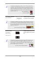
A. Front panel SMBus connecting pin (6-pin FPSMB)
This header allows you to connect SMBus (System Management
peripheral equipment in the system, which has slower
transmission rates, and power management equipment.
B. Internet status indicator (2-pin LAN1_LED, LAN2_LED)
These two 2-pin headers allow you to use the Gigabit internet
indicator cable to connect to the LAN status indicator. When this
C. Chassis intrusion pin (2-pin CHASSIS)
This header is provided for host computer chassis with chassis
intrusion detection designs. In addition, it must also work with
external detection equipment, such as a chassis intrusion
detection sensor or a microswitch. When this function is activated,
if any chassis component movement occurs, the sensor will
immediately detect it and send a signal to this header, and the
system will then record this chassis intrusion event. The default
setting is set to the CASEOPEN and GND pin; this function is off.
D. Locator LED (6-pin LOCATOR)
This header is for the locator switch and LED on the front panel.
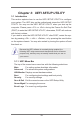
Speaker Header
1
+5V
DUMMY
DUMMY
SPEAKER
Please connect the speaker
to this header.
Front and Rear
Fan Connectors
Please connect the fan
cables to the fan connectors
and match the black wire to
the ground pin. All fans sup-
ports Fan Control.
GND
+12V
CPU_FAN_SPEED
FAN_SPEED_CONTROL
FAN_SPEED
FAN_SPEED_CONTROL
+12V
GND
CPU Fan Connectors
Please connect the CPU fan
cable to the connector and
match the black wire to the
ground pin.
GND
+12V
CPU_FAN_SPEED
FAN_SPEED_CONTROL