775S61 User Manual Version 1.0 Published September 2004 Copyright©2004 ASRock INC. All rights reserved.
Copyright Notice: No part of this manual may be reproduced, transcribed, transmitted, or translated in any language, in any form or by any means, except duplication of documentation by the purchaser for backup purpose, without written consent of ASRock Inc. Products and corporate names appearing in this manual may or may not be registered trademarks or copyrights of their respective companies, and are used only for identification or explanation and to the owners’ benefit, without intent to infringe.
Contents 1 Introduction .................................................... 4 1.1 Package Contents ........................................................... 1.2 Specifications ................................................................. 1.3 Motherboard Layout ....................................................... 1.4 ASRock I/OTM ................................................................... 4 5 7 8 2 Installation ...................................................... 9 2.1 2.2 2.3 2.4 2.
Chapter 1 Introduction Thank you for purchasing ASRock 775S61 motherboard, a reliable motherboard produced under ASRock’s consistently stringent quality control. It delivers excellent performance with robust design conforming to ASRock’s commitment to quality and endurance. Chapter 1 and 2 of this manual contain introduction of the motherboard and step-bystep installation guide for new DIY system builders. Chapter 3 and 4 contain basic BIOS setup and Support CD information.
1.2 Specifications Platform: CPU: Micro ATX Form Factor: 9.6-in x 9.0-in, 24.4 cm x 22.9 cm 775-Pin Socket supporting Intel® Pentium® 4 / Celeron® processor (in 775-land LGA package) Chipsets: North Bridge: SiS 661FX chipset, FSB @ 800/533MHz, supports Hyper-Threading Technology (see CAUTION 1) South Bridge: SiS 963L chipset, supports USB 2.0, ATA 133 VGA: SiS Real256E, 32MB-64MB VRAM (share memory) Memory: 3 DDR DIMM slots: DDR1, DDR2, and DDR3 PC2100 (DDR266) for 3 DDR DIMM slots, Max.
1 RJ 45 port; 4 default USB 2.0 ports; Audio Jack: Line Out / Line In / Microphone + Game port AMI legal BIOS; Supports “Plug and Play”; ACPI 1.1 compliance wake up events; CPU frequency stepless control (only for advanced users’ reference, see CAUTION 5) Microsoft® Windows® 98SE / ME / 2000 / XP compliant BIOS: OS: CAUTION! 1. 2. About the setting of “Hyper Threading Technology”, please check page 23. While CPU overheat is detected, the system will automatically shutdown.
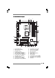
1.3 Motherboard Layout 3 4 1 2 6 5 22.9cm (9.0 in) PS2_USB_PWR1 1 PS/2 Mouse Mic Mic in In ` 2 3 45 LAN PHY ATXPWR1 01 IDE2 IDE1 1.5V_AGP1 Super I/O 8 ATA133 PCI 1 SIS 963L PCI 2 CD1 AUX1 AUDIO1 775S61 1 USB45 1 AUDIO CODEC JR1 JL1 PCI 3 9 10 CMOS Battery 5.1CH USB2.0 CHA_FAN1 22 21 2Mb BIOS 7 24.4cm (9.6 in) Line Line In in 25 24 23 SIS 661FX Chipset Line out Prescott 800 DDR400 FSB800 GAME AUDIO1 AUDIO1 GAME USB 2.
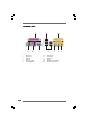
1.4 ASRock I/O TM 1 2 3 4 5 8 Parallel Port RJ-45 Port Game Port Microphone (Pink) Line In (Light Blue) 6 7 8 9 10 Line Out (Lime) USB 2.
Chapter 2 Installation 775S61 is a Micro ATX form factor (9.6" x 9.0", 24.4 x 22.9 cm) motherboard. Before you install the motherboard, study the configuration of your chassis to ensure that the motherboard fits into it. Make sure to unplug the power cord before installing or removing the motherboard. Failure to do so may cause physical injuries to you and damages to motherboard components. 2.1 Screw Holes Place screws into the holes indicated by circles to secure the motherboard to the chassis.
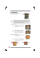
2.3 CPU Installation For the installation of Intel 775-Pin CPU, please follow the steps below. 775-Pin Socket Overview Before you insert the 775-Pin CPU into the socket, please check if the CPU surface is unclean or if there is any bent pin on the socket. Do not force to insert the CPU into the socket if above situation is found. Otherwise, the CPU will be seriously damaged. Step 1. Open the socket: Step 1-1. Disengaging the lever by depressing down and out on the hook to clear retention tab. Step 1-2.
For proper inserting, please ensure to match the two orientation key notches of the CPU with the two alignment keys of the socket. Step 2-3. Carefully place the CPU into the socket by using a purely vertical motion. Step 2-4. Verify that the CPU is within the socket and properly mated to the orient keys. Step 3.
2.4 Installation of CPU Fan and Heatsink This motherboard is equipped with 775-Pin socket that supports Intel 775-Pin CPU. Please adopt the type of heatsink and cooling fan compliant with Intel 775-Pin CPU to dissipate heat. Before you installed the heatsink, you need to spray thermal interface material between the CPU and the heatsink to improve heat dissipation. Ensure that the CPU and the heatsink are securely fastened and in good contact with each other.
2.5 Installation of Memory Modules (DIMM) 775S61 motherboard provides three 184-pin DDR (Double Data Rate) DIMM slots. Please make sure to disconnect power supply before adding or removing DIMMs or the system components. Step 1. Step 2. Unlock a DIMM slot by pressing the retaining clips outward. Align a DIMM on the slot such that the notch on the DIMM matches the break on the slot. notch break notch break The DIMM only fits in one correct orientation.
2.6 Expansion Slots (PCI, AMR, and AGP Slots) There are 3 PCI slots, 1 AMR slot, and 1 AGP slot on 775S61 motherboard. PCI slots: The PCI slots are used to install expansion cards that have the 32-bit PCI interface. AMR slot: The AMR slot is used to insert an ASRock MR card with v.92 Modem functionality. AGP slot: The AGP slot is AGP 3.5 compliant and it supports an 8X / 4X AGP card. Do NOT use a 3.
2.7 Jumpers Setup The illustration shows how jumpers are setup. When the jumper cap is placed on pins, the jumper is “SHORT”. If no jumper cap is placed on pins, the jumper is “OPEN”. The illustration shows a 3-pin jumper whose pin1 and pin2 are “SHORT” when jumper cap is placed on these 2 pins. Jumper PS2_USB_PWR1 Description Short pin2, pin3 to enable (see p.7 item 1) +5VSB (standby) for PS/2 or +5V +5VSB USB wake up events.
2.8 Onboard Headers and Connectors Connectors are NOT jumpers. DO NOT place jumper caps over these connectors. FDD Connector (33-pin FLOPPY1) FLOPPY1 Pin1 (see p.7, No. 19) the red-striped side to Pin1 Note: Make sure the red-striped side of the cable is plugged into Pin1 side of the connector. Primary IDE Connector (Blue) Secondary IDE Connector (Black) (39-pin IDE1, see p.7, No. 9) (39-pin IDE2, see p.7, No.
Front panel audio connector GND +5VA BACKOUT-R BACKOUT-L (9-pin AUDIO1) (see p.7 item 22) 1 AUD-OUT-L GND AUD-OUT-R MIC-POWER MIC System panel connector PLED+ PLEDPWRBTN# GND (9-pin PANEL1) (see p.7 item 12) 1 This is an interface for front panel audio cable that allows convenient connection and control of audio devices. This connector accommodates several system front panel functions. DUMMY RESET# GND HDLEDHDLED+ Chassis speaker connector 1 SPEAKER DUMMY DUMMY +5V (4-pin SPEAKER 1) (see p.
Chapter 3 BIOS Setup 3.1 BIOS Setup Utility This section explains how to configure your system using the BIOS Setup Utility. The Flash Memory on the motherboard stores the BIOS Setup Utility. When you start up the computer, there is a chance for you to run the BIOS Setup. Press during the Power-On-Self-Test (POST) to enter the BIOS Setup Utility, otherwise, POST continues with its test routines.
Navigation Key(s) / / + / Function Description Displays the General Help Screen Jumps to the Exit menu or returns to the upper menu from the current menu Moves cursor up or down between fields Selects menu to the left or right Increases or decreases values Brings up a selected menu for a highlighted field Loads all the setup items to default value Saves changes and exits Setup 3.2 Main Menu When you enter the BIOS Setup Utility, the following screen appears.
TYPE To set the type of the IDE device, first, please select “IDE Devices” on Main menu and press to get into the sub-menu. Then, select among “Primary IDE Master”, “Primary IDE Slave”, “Secondary IDE Master”, and “Secondary IDE Slave” to make configuration of its type. Below are the configuration options. AMIBIOS SETUP UTILITY - VERSION 3.
[CD/DVD]: This is used for IDE CD/DVD drives. [ARMD]: This is used for IDE ARMD (ATAPI Removable Media Device), such as MO. Cylinders This is used to configure the number of cylinders. Refer to the drive documentation to determine the correct value. Heads This is used to configure the number of read/write heads. Refer to the drive documentation to determine the correct values. Write Pre-compensation Enter Write Pre-compensation sector. Refer to the drive documentation to determine the correct value.
Chapter 4 Software Suppor Supportt 4.1 Install Operating System This motherboard supports various Microsoft® Windows® operating systems: 98 SE / ME / 2000 / XP. Because motherboard settings and hardware options vary, use the setup procedures in this chapter for general reference only. Refer to your OS documentation for more information. 4.2 Support CD Information The Support CD that came with the motherboard contains necessary drivers and useful utilities that enhance the motherboard features. 4.2.
Appendix: Advanced BIOS Setup This section will introduce you the following BIOS Setup menus: “Advanced,” “Security,” “Power,” “Boot,” and “Exit.” 1. Advanced BIOS Setup Menu Main Advanced AMIBIOS SETUP UTILITY - VERSION 3.
Chipset Configuration: AMIBIOS SETUP UTILITY - VERSION 3.31a Advanced Chipset Configuration [ Setup Help ] AGP Aperture Size Onboard VGA Share Memory 64MB Auto USB Controller USB Device Legacy Support USB 2.0 Controller Enabled Disabled Enabled DRAM CAS# Latency MA 1T/2T Select Vccm Voltage Auto MA2T 2.
No-Excute Memory Protection: No-Execution (NX) Memory Protection Tech nology is an enhancement to the IA-32 Intel Architecture. An IA-32 proces sor with “No Execute (NX) Memory Protection” can prevent data pages from being used by malicious software to execute code. This option will be hidden if the current CPU does not support No-Excute Memory Protection.
Resource Configuration: AMIBIOS SETUP UTILITY - VERSION 3.31a Advanced Resource Configuration PCI Latency Timer (PCI Clocks) Primary Graphics Adapter F1:Help Esc:Previous Menu :Select Item [ 32 PCI +/-:Change Values Enter:Select Sub-Menu Setup Help ] to select PCI clocks. Leave on default setting for the best PCI performance. F9:Setup Defaults F10:Save & Exit PCI Latency Timer (PCI Clocks): The default is 32.
OnBoard Parallel Port: Select Parallel Port address or disable Parallel Port. Configuration options: [Auto], [Disabled], [378], [278]. Parallel Port Mode: Set the operation mode of the parallel port. The default value is [ECP+EPP]. If this option is set to [ECP+EPP], it will show the EPP version in the following item, “EPP Version”. OnBoard Midi Port: Select address for Midi Port or disable Midi Port. Midi IRQ Select: Use this to select Midi IRQ.
2. Security Setup Menu Main AMIBIOS SETUP UTILITY - VERSION 3.31a Boot Power Exit Security Advanced [ Supervisor Password User Password Clear Clear Set Supervisor Password Set User Password [ Enter ] [ Enter ] Password Check Setup F1:Help Esc:Exit :Select Item :Select Menu Setup Help ] to set the supervisor password. +/-:Change Values Enter:Select Sub-Menu F9:Setup Defaults F10:Save & Exit Supervisor Password: This field shows the status of the Supervisor Password.
3. Power Setup Menu Main Advanced AMIBIOS SETUP UTILITY - VERSION 3.
4. Boot Setup Menu Main AMIBIOS SETUP UTILITY - VERSION 3.31a Boot Power Exit Security Advanced [ Quick Boot Mode Boot Up Num-Lock Boot To OS/2 Boot From Network Enabled On No Disabled Setup Help ] to enable or disable the quick boot mode. Boot Device Priority F1:Help Esc:Exit :Select Item :Select Menu +/-:Change Values Enter:Select Sub-Menu F9:Setup Defaults F10:Save & Exit Quick Boot Mode: Enable this mode will speed up the boot-up routine by skipping memory retestings.
5. Exit Menu Main Advanced AMIBIOS SETUP UTILITY - VERSION 3.31a Boot Power Exit Security Exit Saving Changes Exit Discarding Changes Load Default Settings Discard Changes F1:Help Esc:Exit [ [ [ [ Enter Enter Enter Enter :Select Item :Select Menu [ ] ] ] ] Setup Help ] Exits and saves the changes to CMOS RAM +/-:Change Values Enter:Select Sub-Menu F9:Setup Defaults F10:Save & Exit Exit Saving Changes: After you enter the sub-menu, the message “Save current settings and exit” will appear.